GD62 IP67 Outdoor LoRaWAN Gateway User Manual
Document version: 1.2
Applies to: GD62 IP67 outdoor LoRaWAN gateways. Check the device label and delivery list for the radio region, cellular options and power configuration.
1. Product Overview
The GD62 IP67 outdoor LoRaWAN gateway receives and forwards LoRaWAN terminal traffic to a network platform. It is intended for campuses, industrial sites, building perimeters and other outdoor IoT installations.
The gateway uses an ESP32-S3 controller and supports Ethernet, 2.4 GHz Wi-Fi and optional 4G backhaul. The gwTool6 Web console provides network, LoRaWAN server, radio and maintenance settings.
The product has an IP67 enclosure and an operating temperature range of -20 °C to 60 °C. Wall and pole mounting are supported. Seal every cable entry, antenna connection, service opening and unused port before operation.
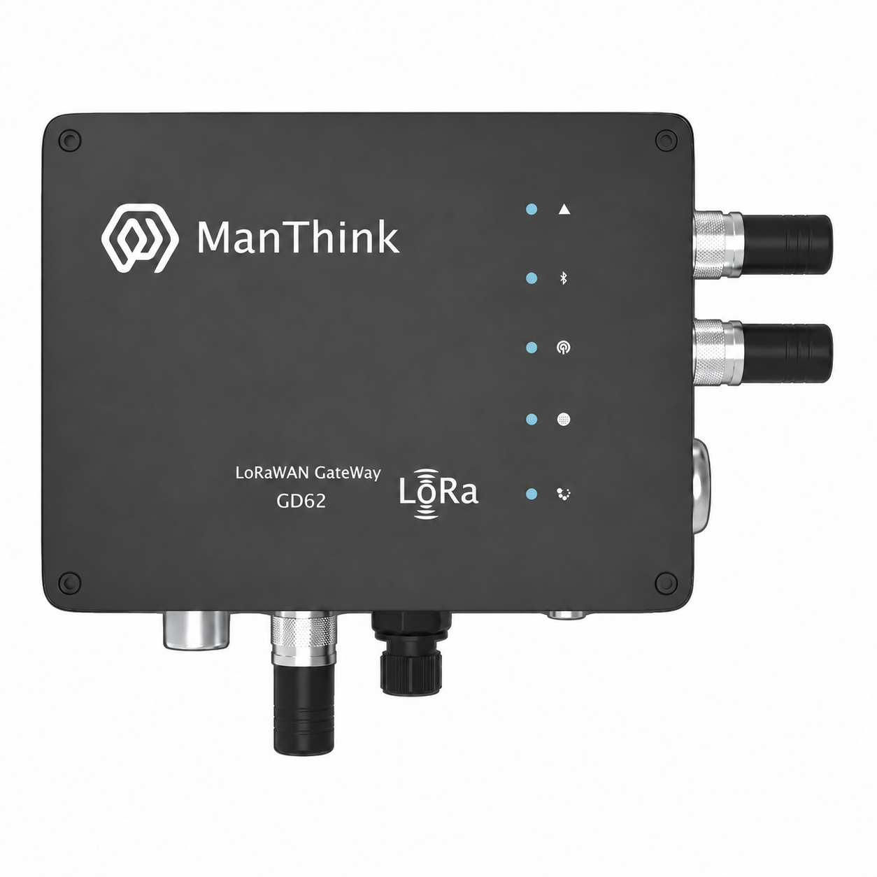
Figure 1: GD62 enclosure illustration. Ports, antennas and indicators depend on the delivered configuration; enclosure markings do not imply that every function is fitted.
1.1 Features
- ESP32-S3 controller with 8 MB Flash and 8 MB PSRAM.
- Semtech SX1301 or SX1302 concentrator, according to the supplied configuration.
- Single LoRa antenna, eight receive frequencies and half-duplex operation.
- Ethernet and Wi-Fi STA backhaul, with optional 4G cellular connectivity.
- Semtech UDP Packet Forwarder, Basic Station and MQTT Bridge support.
- Local Wi-Fi AP configuration and a Chinese/English Web console.
- Web OTA, runtime logs and factory reset.
- IP67 enclosure for fixed outdoor installation.
2. Technical Specifications
| Category | Parameter | Specification |
|---|---|---|
| Product identification | Model | GD62 |
| Computing | Controller | ESP32-S3 |
| Computing | Flash / PSRAM | 8 MB / 8 MB |
| LoRaWAN | Concentrator | Semtech SX1301 or SX1302, as supplied |
| LoRaWAN | Receive frequencies | 8 |
| LoRaWAN | Antenna and mode | Single LoRa antenna, half-duplex |
| LoRaWAN | Radio variant | 400 MHz class or 800 MHz and above, as ordered |
| LoRaWAN | Regional profiles | Hardware variants for CN470, EU433, EU868, AS923, AU915 and US915 |
| LoRaWAN | Forwarding protocols | Semtech UDP, Basic Station, MQTT Bridge |
| Network | Ethernet | 10/100 Mbps; DHCP and static IPv4 |
| Network | Wi-Fi | 2.4 GHz, AP / STA |
| Network | Cellular backhaul | Optional 4G; module, bands and operator support as supplied |
| Network | Link management | Ethernet and Wi-Fi STA failover; cellular variants add 4G; Ethernet has default priority |
| Management | Configuration | gwTool6 Web console |
| Management | Time synchronization | SNTP |
| Management | Firmware maintenance | Web OTA with A/B firmware partitions |
| Environment and enclosure | Protection rating | IP67 |
| Environment and enclosure | Operating temperature | -20 °C to 60 °C |
| Environment and enclosure | Enclosure dimensions | 164 × 124 × 50 mm; allow installation clearance according to the supplied drawing |
| Environment and enclosure | Mounting | Wall or pole |
The radio region must match the hardware, antenna and terminals. Some supplied model codes use US902 for the US915 regional parameters covering 902–928 MHz. Transmit power, sensitivity, power consumption and weight are specified in the delivery specification.
3. Before Installation
Check the device label, radio region, power requirements and packing list. Prepare a compatible LoRa antenna, power supply, mounting bracket, sealing components and any required Ethernet cable. Cellular backhaul also requires a SIM with an active data plan.
- Disconnect power before installing antennas, the SIM or power wiring.
- Connect the LoRa antenna before power-up. Do not start LoRa transmission without an antenna.
- Choose a secure, accessible location with suitable radio coverage, away from standing water and heat sources.
- Keep the actual ambient temperature at the installation location within -20 °C to 60 °C.
- Do not connect multiple power sources unless explicitly permitted by the delivery documentation.
- Do not disconnect power during firmware updates, configuration writes or factory reset.
4. Interfaces and Power
GD62 has no external REC button. For factory reset, see the service instructions in Section 9.3.
Available interfaces vary by delivery configuration. Identify each interface by its device label. Keep unconfigured or unused openings sealed with the original components.
| Interface or function | Purpose and precautions |
|---|---|
| LoRa | Connect a LoRa antenna matching the gateway region |
| Ethernet | Connect a switch or router for wired backhaul |
| PoE | Available only on PoE-equipped variants; use a supply matching the delivery specification |
| SIM | Cellular variants only; follow the actual slot markings for card size and orientation |
| Wi-Fi / 4G antenna | Install according to the supplied antenna configuration; positions and antenna types depend on the delivered unit |
| Type-C | Where fitted, supports 5 V power and local maintenance; reseal the service opening after use |
| DC input | Where fitted, supports 5–24 V DC; follow the polarity markings |
| A+ / B- | If present, reserved RS-485 interface; no user application function in the current version |
Before connecting PoE, check its power standard, voltage and wiring requirements. Do not select a power source solely by the port name. Never apply more than 5 V to Type-C or connect power to A+ or B-.
Install PoE injectors and other supplies without a stated outdoor rating in a dry location or suitable protective cabinet.
5. Installation and Power-Up
5.1 Mount the Gateway
For wall mounting, mark the supplied bracket holes and use fasteners appropriate for the wall material. For pole mounting, confirm that the pole diameter fits the supplied clamp and tighten the clamp evenly.
Follow the supplied installation drawing for orientation. Allow space for antennas, connectors and cable bends. Provide cable support so that connectors do not carry the cable weight. Do not open the enclosure or modify its seals without authorization.
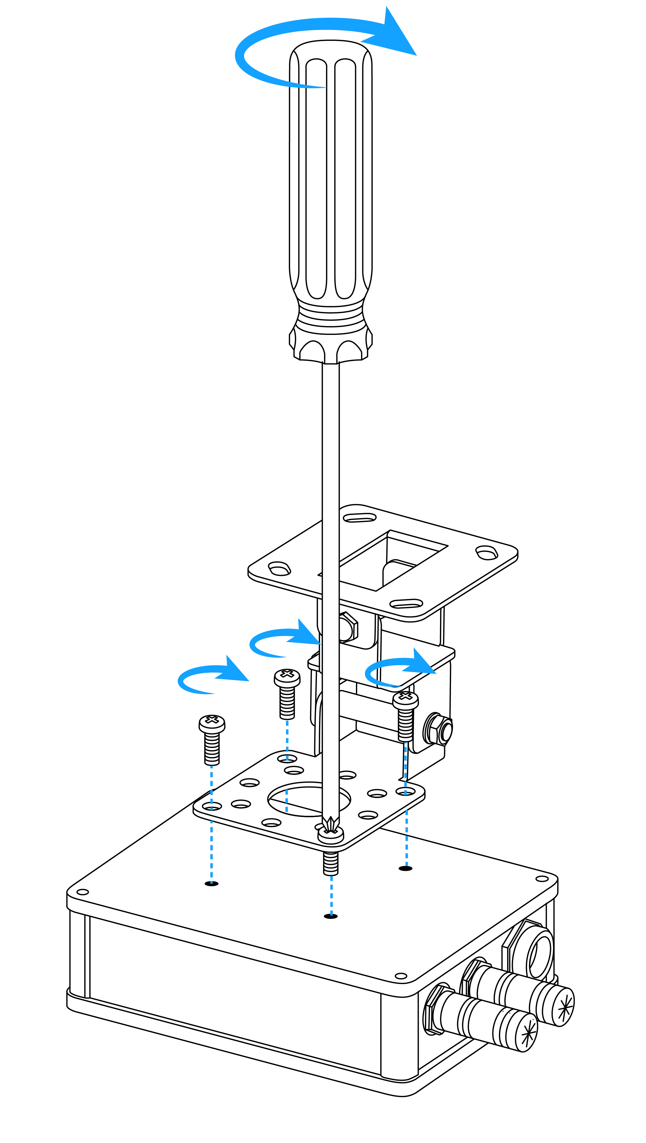
Figure 2: Bracket and backplate assembly. Use the supplied fasteners and installation drawing for wall or pole mounting.
5.2 Install Antennas and SIM
- Disconnect power and verify that the LoRa antenna matches the radio band.
- Attach and tighten the antenna at the corresponding port without forcing or twisting the connector.
- Where external Wi-Fi or 4G antennas are supplied, connect them to the matching labeled ports.
- For cellular backhaul, insert the SIM according to the actual slot markings and reinstall the waterproof cover.
5.3 Connect Ethernet and Power
- Thread the waterproof connector components onto the cable in the supplied assembly order.
- Insert the RJ45 plug, then fit the seals and tighten the waterproof connector.
- For PoE, connect the compatible supply output to the gateway and connect its data input according to the site network plan.
- For separate DC or Type-C power, confirm the permitted input and polarity for the variant and seal the power entry.
- Complete the sealing checks, apply power and allow the system to start.
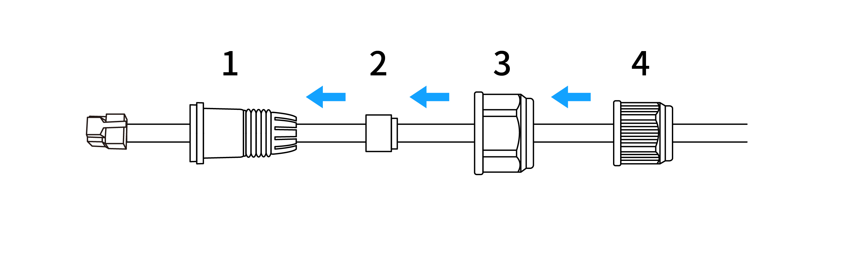
Figure 3: Ethernet cable sealing assembly. Fit and tighten the supplied sealing parts in order, ensuring that the seal matches the cable diameter.
5.4 Sealing Checks
- Seals are present, correctly seated and free from pinching or visible aging.
- Waterproof connectors fit the cable diameter and cable entries are secure.
- Antenna connections and service openings are sealed; original waterproof caps are installed on unused ports.
- Cables have drip loops to prevent water from running toward the connectors.
- Brackets and fasteners are secure, with no abnormal strain on cables or connectors.
IP67 protection requires an intact enclosure and correctly assembled seals and connectors. The device is not intended for continuous immersion. Do not direct high-pressure water at the interfaces.
6. First Login
6.1 Access over Ethernet
The gateway can obtain an address through DHCP by default. Find the assigned IP address in the router or DHCP server, then open http://<gateway-IP-address> from the same network.
6.2 Access over Wi-Fi AP
| Item | Factory default |
|---|---|
| AP name | GD6-<Gateway EUI> |
| AP password | wifi!0804 |
| Management address | http://192.168.4.1 |
| Web login password | wifi!0804 |
Connect to the configuration AP, open the management address and log in. The SSID falls back to LGW-Config only when a valid Gateway EUI is unavailable. If commissioning staff have changed these settings, use the delivery record.
Change the Web and AP passwords after first login. They are managed independently. Changing AP settings may disconnect the current session; reconnect with the new settings.
7. Configure Backhaul
7.1 Ethernet
Open the Ethernet page and select DHCP or enter a static IP, subnet mask, gateway and DNS. After saving a static address, confirm that an alternative management link is available, then reboot to activate the new address.
The Ethernet controller power setting does not provide external PoE output. Disabling the interface interrupts its management and data connections.
7.2 Wi-Fi STA
On the Wi-Fi page, scan for the site's 2.4 GHz network, enter its password, save and confirm that a valid IP address is obtained. Disabling Wi-Fi affects both the AP and STA; prepare an alternative management link first.
7.3 4G
On cellular variants, insert the SIM and enable the module on the cellular page. Configure the APN as required by the operator. Enter the correct PIN if the SIM requires one. Keep serial settings consistent with the supplied module. After saving, check network registration, signal and the assigned data connection address.
8. Connect to a LoRaWAN Platform
- Create the gateway on the target platform using the device's Gateway EUI.
- Open LoRaWAN NS in gwTool6 and select the provider and protocol.
- Enter the platform's server address, ports and authentication material.
- Match the platform channel plan, terminal frequencies and gateway region.
- Save and apply, wait for forwarding to resume and confirm that the gateway is online.
- Send traffic from a registered terminal and verify uplinks on the platform. Verify downlinks when required by the application.
| Connection method | Main settings |
|---|---|
| Semtech UDP | Server address, uplink port and downlink port |
| ThinkLink MQTT | Broker URI, Client ID, credentials, topics and TLS settings |
| Basic Station LNS | LNS address, trust certificate and platform authentication material |
| Basic Station CUPS | CUPS address and corresponding authentication material |
Basic Station LNS uses a wss:// address; CUPS uses https://. Configure LoRaWAN data transport separately from the remote-configuration MQTT connection.
Basic Station and Packet Forwarder are mutually exclusive. Switching drivers briefly interrupts forwarding. Basic Station uses the channel plan supplied by the server; local radio settings apply to Packet Forwarder. Software settings cannot convert hardware to a different radio band.
9. Maintenance and Recovery
9.1 Routine Maintenance
Check platform connectivity, backhaul, logs and terminal traffic. Inspect brackets, cables and seals periodically, and address looseness, aging or damage. If water ingress is found, disconnect power and arrange service. Restore sealing before returning the gateway to operation.
9.2 Firmware Update
Record network and platform settings before updating. Confirm the device model, hardware revision, region and firmware compatibility. Upload the matching .bin through Web OTA, wait for validation, writing and reboot, then verify the version and key settings. Do not refresh the page or interrupt network or power during the update.
Do not upload a full manufacturing Flash image as a Web OTA package. Filesystem maintenance requires a controlled service procedure; do not delete or overwrite Web assets yourself.
9.3 Factory Reset
Factory reset restores network, LoRaWAN and system settings. Record required settings and ensure that the gateway can be reconfigured before proceeding.
GD62 has no external REC button, so factory reset cannot be performed using an external button. Contact technical support and follow the supplied service procedure if a factory reset is required. Do not open the IP67 enclosure to find or press an internal button, as this can compromise its seals.
The default Web password returns to wifi!0804; the programmed Gateway EUI is retained. Change the password and restore network, platform and radio settings after login.
9.4 Operating Indication
Variants with standard operating indication flash slowly during normal operation, with a default pattern of 1 second on and 1 second off. Identify visible indicators according to the delivered unit. Confirm connectivity and forwarding through the console and platform status as well.
10. Troubleshooting
| Symptom | Checks and actions |
|---|---|
| No power | Check the supply, PoE compatibility, Ethernet cable and connections |
| AP not found | Look for GD6-<Gateway EUI> and confirm that the AP is enabled |
| Management page unavailable | Check the DHCP address, client subnet or AP connection |
| Static IP not active | Confirm settings were saved, prepare another management link and reboot |
| Wi-Fi STA cannot connect | Check the 2.4 GHz SSID, password, signal and DHCP |
| 4G cannot connect | Check SIM, PIN, APN, antenna, signal and module bands |
| Platform reports offline | Check backhaul, Gateway EUI, protocol, addresses and authentication |
| Gateway online but no terminal data | Check LoRa antenna, region, channel plan and terminal registration |
| Basic Station connection fails | Check system time, URI, certificates and authentication |
| Brief outage after protocol change | Wait for forwarding to resume, then check active settings and logs |
When contacting support, provide the model, hardware and firmware versions, incident time, symptoms and relevant logs. Remove passwords, tokens, private keys and site network identifiers before sharing information publicly.
11. Related Documents
- gwTool6 Configuration Guide
- Connect to ChirpStack through Basic Station
- Connect to TTN through Basic Station