gwTool7 Gateway Administrator Manual
Product: gwTool GD7
Document version: 1.0
Screenshot language: English
Screenshot source: authorized test device; device identifiers, network addresses, and account information have been cropped or masked
This manual is intended for distributors, system administrators, and field engineers. It explains how to inspect status, configure the gateway through the gwTool web interface, and recognize operations that require extra care.
IMPORTANT
Fields and page layouts may vary slightly between firmware versions. Back up the current configuration and schedule a maintenance window before changing settings, upgrading software, or rebooting the gateway.
Contents
- 1. Sign-in, Sign-out, and Language
- 2. Overview
- 3. LoRaWAN
- 4. ThinkLink
- 5. COM and Serial Services
- 6. Network
- 7. System
- 8. Upgrade
- 9. Maintenance
- 10. General Safety and Recovery
1. Sign-in, Sign-out, and Language
Purpose
The sign-in page authenticates an administrator before opening the gateway console. After signing in, the interface language can be changed from the selector in the upper-right corner.
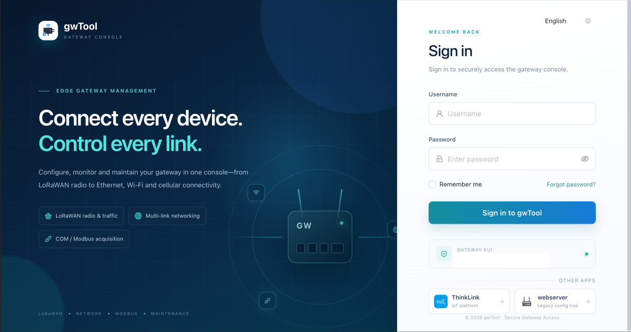
Figure 1: English sign-in page. The form is empty, and the gateway identifier has been masked.
Sign-in Procedure
- Connect the management computer to a network that is allowed to reach the gateway console.
- Open
http://<gateway-management-address>/in a browser. - Enter the administrator username and password, then select Sign in to gwTool.
- Confirm that the left navigation and the language selector appear.
Change Language and Sign Out
- Use the language selector in the upper-right corner to switch between English and the available Chinese interfaces.
- After switching, verify that the page title and navigation labels have changed before continuing.
- When administration is complete, sign out from the account menu. Do not rely on closing the browser tab alone.
Verification
- Success: the Overview page opens, the navigation is available, and no session-expired message appears.
- Failure: check the management address, network path, account status, and keyboard case. Do not repeatedly try an uncertain password.
WARNING
Do not save administrator credentials on a shared computer or transmit them through screenshots, chat messages, or support tickets.
2. Overview
Navigation: Overview
Purpose
The Overview page summarizes gateway identity, the primary network link, local services, software versions, and resource utilization. Use it for a health check before configuration or maintenance.
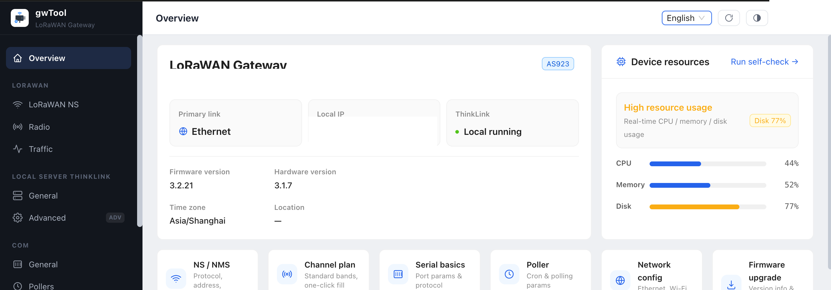
Figure 2: Gateway, network, service, and resource status. Unique identifiers, active addresses, and account information are masked.
Key Areas
| Area | Description | Administrator check |
|---|---|---|
| LoRaWAN Gateway | Region and basic gateway status | Confirm that the regional setting matches the deployment site |
| Primary link | Network currently preferred by the gateway | Confirm that the link type matches the site design |
| ThinkLink | Local service state | Record an abnormal state before troubleshooting |
| Version and device information | Firmware, hardware, and time-zone information | Record versions before upgrades or support escalation |
| Device resources | CPU, memory, and disk usage | Investigate sustained high utilization |
Procedure and Verification
- Open Overview and wait for all status cards to load.
- Check the primary link and ThinkLink state.
- Review CPU, memory, and disk usage; record the time and affected resource if an alert is present.
- Continue to the relevant network, service, or upgrade page only after identifying the affected area.
CAUTION
Overview values represent the most recent refresh. Reload the page and confirm that an alert is still present before maintenance.
3. LoRaWAN
3.1 LoRaWAN NS
Navigation: LORAWAN → LoRaWAN NS
This page selects where the gateway sends LoRaWAN data: a local server or a remote network-server platform. Tabs are provided for the NS1 primary server, NS2 backup, and NMS management.
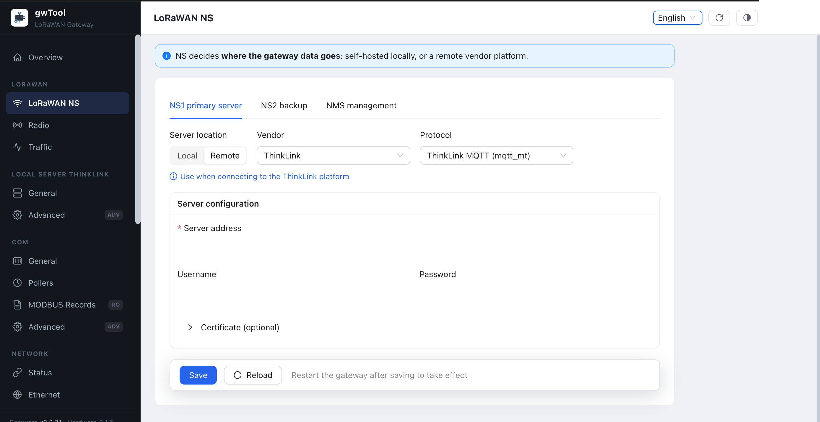
Figure 3: NS1 primary-server configuration. Server address, username, and password values are masked.
Key fields: server location, vendor, protocol, server address, username, password, and optional certificates. UDP normally also requires uplink and downlink ports. MQTT uses a Broker endpoint, while Basic Station uses the Server URI field.
Current gwTool7 firmware offers ChirpStack and The Things Network in Remote mode. Use BasicStation LNS for ChirpStack. For TTN, select BasicStation LNS or BasicStation CUPS according to the deployment design.
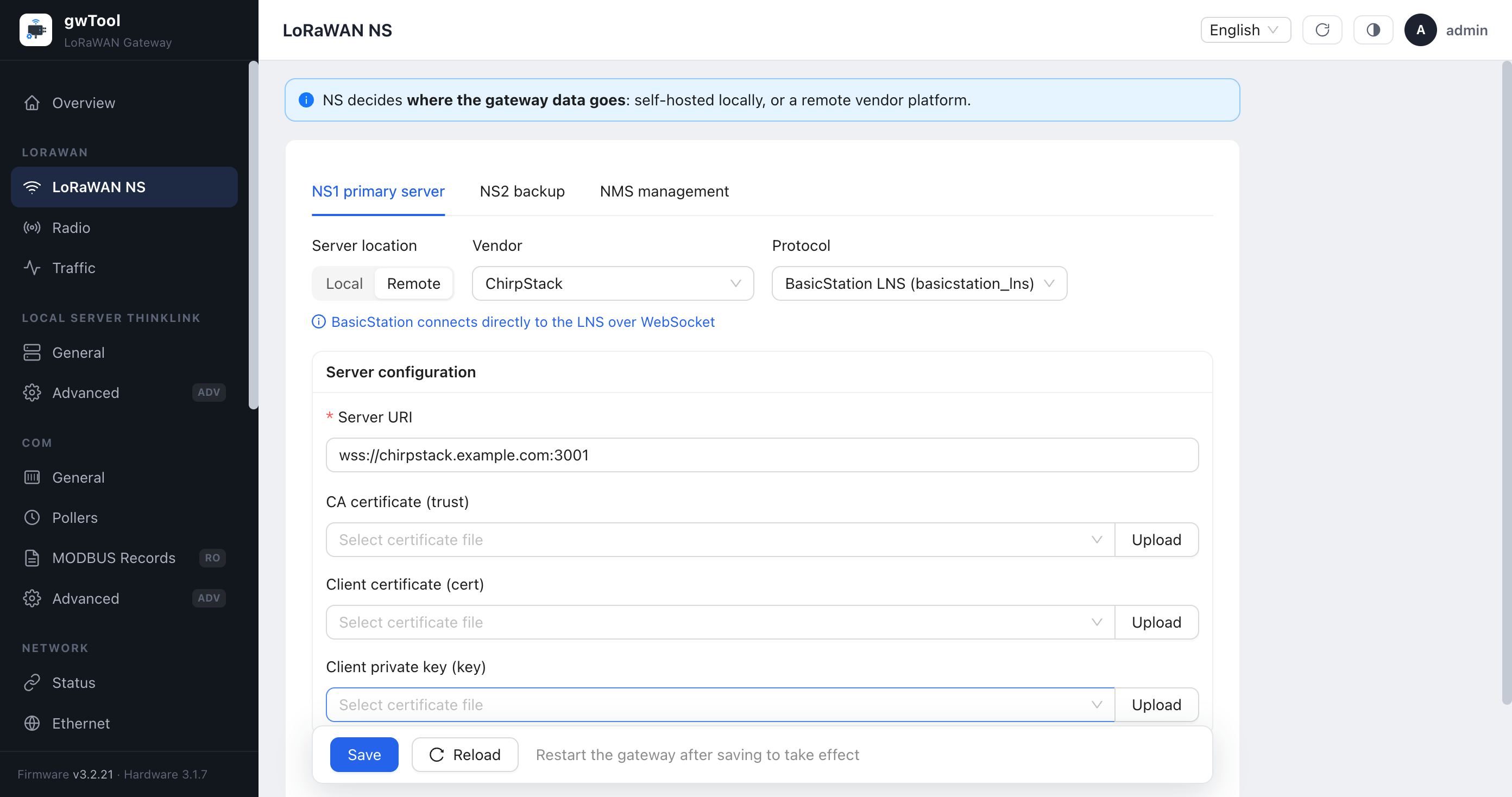
Figure 3A: ChirpStack BasicStation LNS example. The endpoint is a documentation-only example and certificate fields are empty.
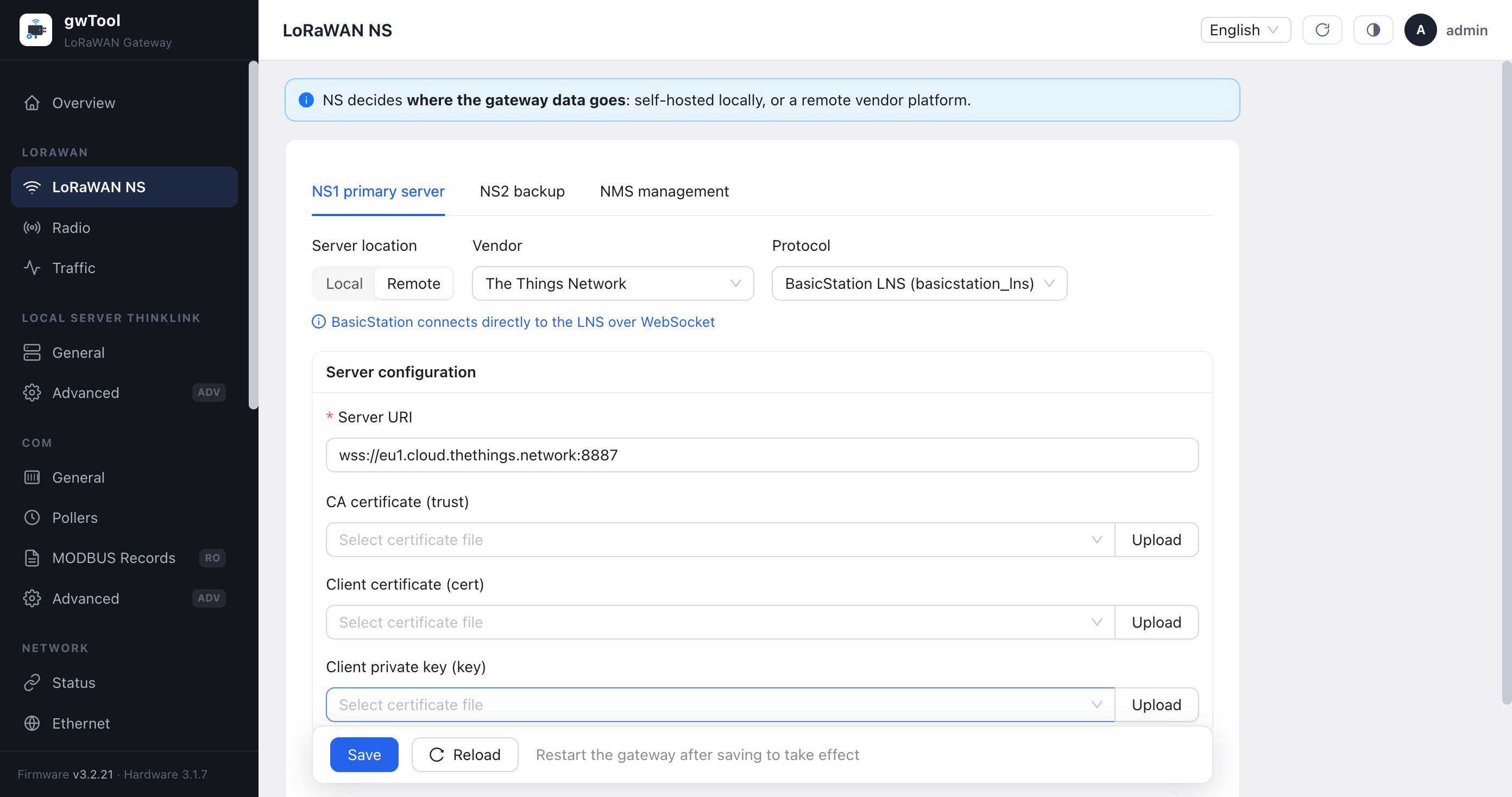
Figure 3B: TTN BasicStation LNS example. Use the actual Server Address, trust certificate, and key supplied through the TTN Console.
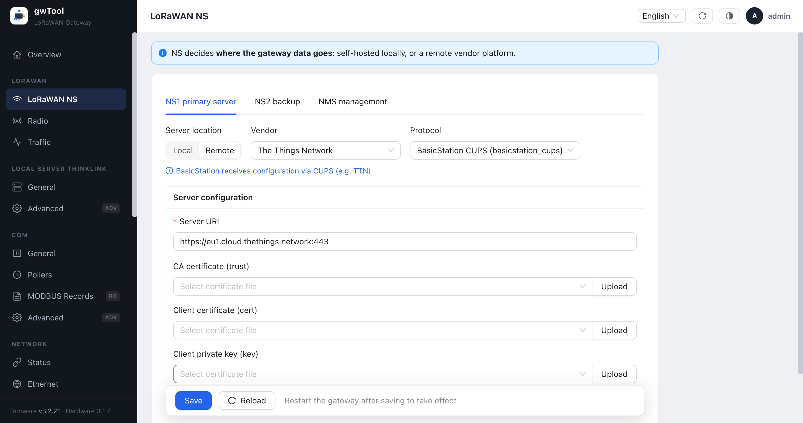
Figure 3C: TTN BasicStation CUPS example. CUPS delivers the LNS settings to the gateway.
Procedure and verification:
- Record the existing NS configuration and obtain the approved protocol, address, ports, and credentials from the platform owner.
- Select the vendor and protocol in NS1, then complete the fields required by that protocol. See the dedicated ChirpStack Basic Station guide and TTN Basic Station guide for the full procedures.
- A blank password field normally preserves the stored value; enter a new one only when rotating credentials.
- Save, wait for the related service to recover, then verify uplink and downlink traffic on both the Traffic page and the server platform.
WARNING
NS2, certificate, and mode controls may be wired differently across firmware releases. A visible control does not prove that a configuration is active; verify traffic after saving.
3.2 Radio
Navigation: LORAWAN → Radio
Use this page to select the regional standard, set keepalive and status-report intervals, and configure channel-plan frequencies, bandwidth, and spreading factors.
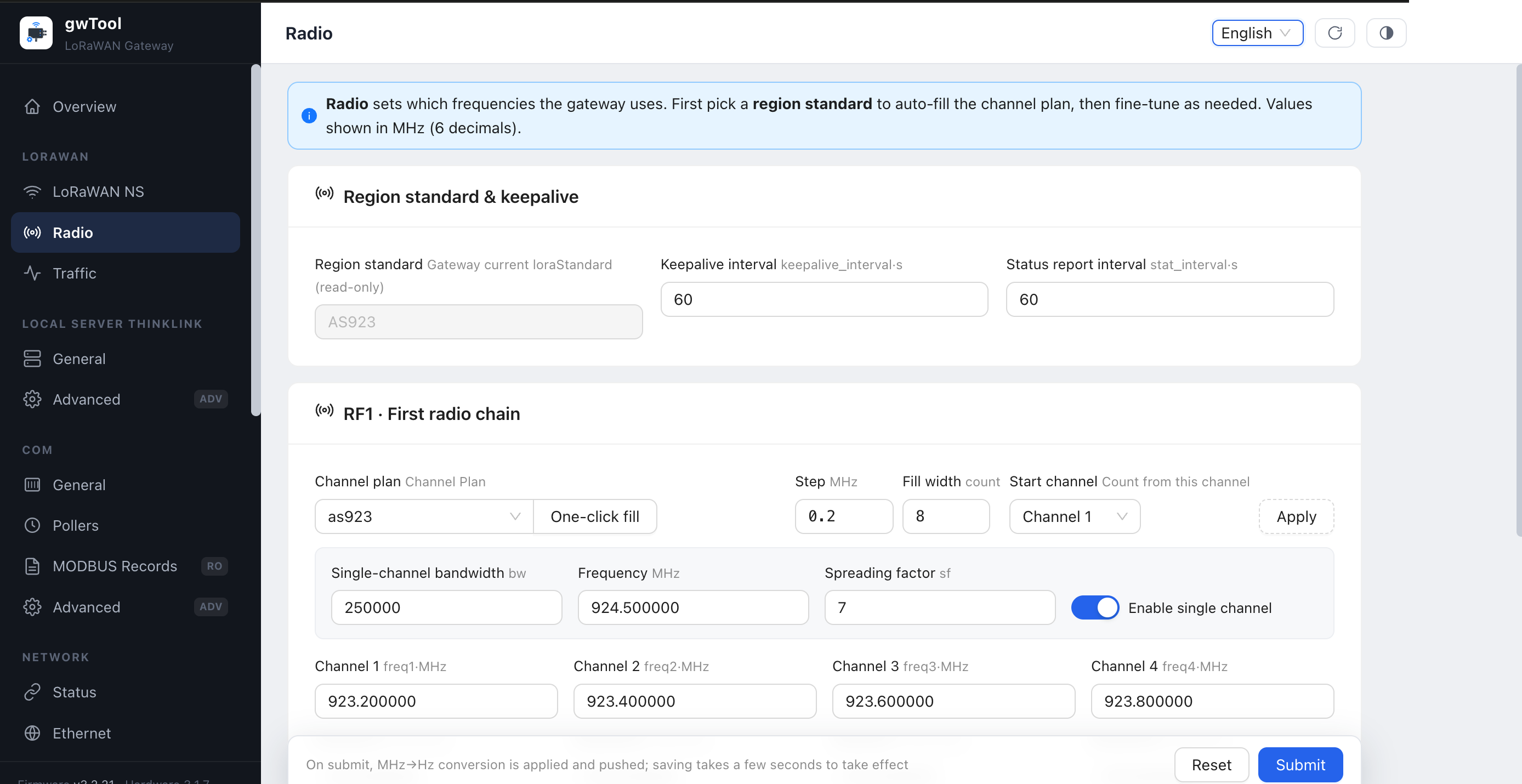
Figure 4: Example AS923 channel plan. Actual frequencies must comply with local regulations and the network plan.
Procedure and verification:
- Confirm the LoRaWAN regional standard permitted at the deployment location.
- Select the matching band plan and use the one-click fill function before applying operator-specific adjustments.
- Verify RF1/RF2, single-channel bandwidth, frequency, spreading factor, and every channel frequency.
- Submit the change, wait several seconds, reload the page, and verify device joins and traffic.
CAUTION
Incorrect frequencies can prevent devices from joining and may violate radio regulations. Preserve the original channel plan before making changes.
3.3 Traffic
Navigation: LORAWAN → Traffic
Traffic provides a live view of uplink and downlink LoRaWAN frames. Filter by all, uplink, or downlink, and expand a record to inspect raw and decoded data.
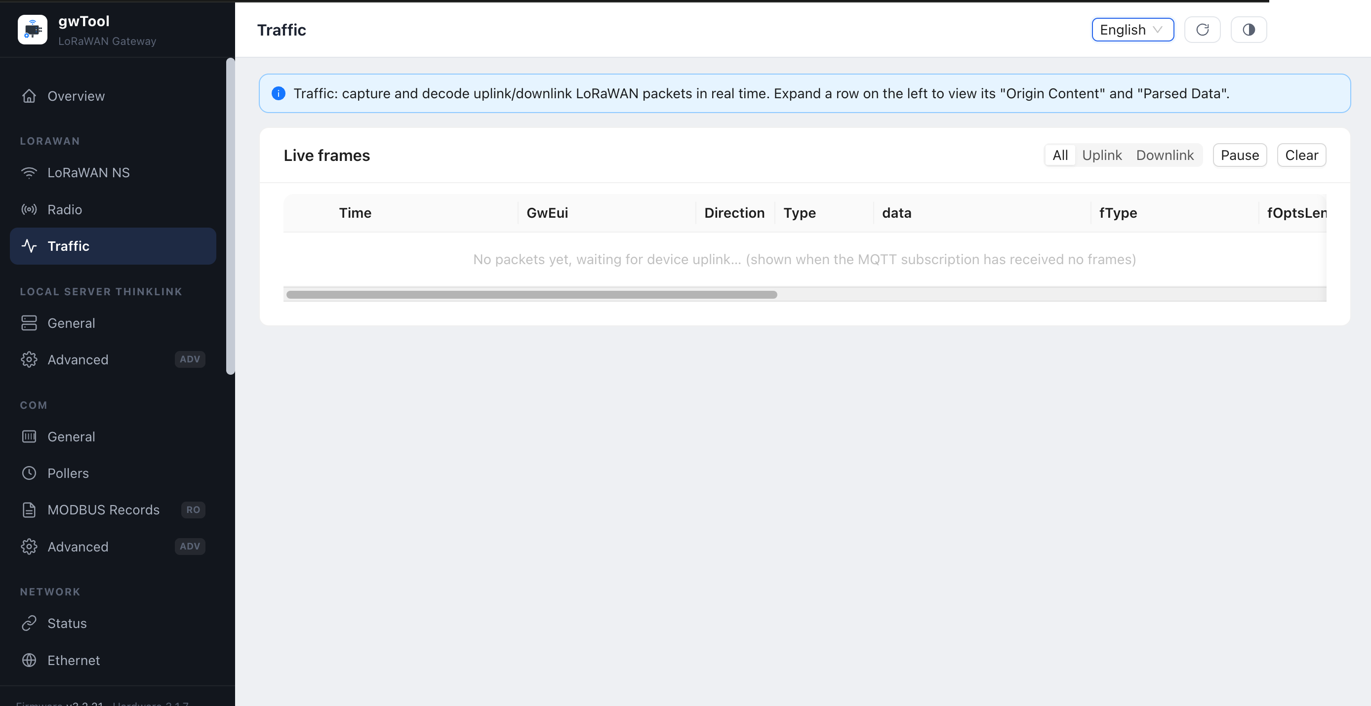
Figure 5: Idle live-traffic table. No field payload is included in the screenshot.
Procedure and verification:
- Keep the page open and trigger a known end-device uplink.
- Filter by direction and confirm the time, gateway reference, direction, and frame type.
- Expand the target row to inspect the raw and decoded content. Pause or clear the list before starting a new observation period.
IMPORTANT
Frames may contain device identifiers and business data. Redact them according to organizational data-handling rules before exporting or taking screenshots.
4. ThinkLink
4.1 ThinkLink General
Navigation: LOCAL SERVER THINKLINK → General
Use this page to enable the local ThinkLink server, control downlink capability, and review core-service and local-connection status.

Figure 6: Local-server controls, service state, and connection area. Connection values are masked.
Procedure and verification:
- Decide whether the local ThinkLink server should be enabled according to the deployment architecture.
- Enable downlink only when the service is authorized to send data to end devices.
- Refresh and verify
lws-thinkOne,tkl-main, and bridge-service states. - Open the ThinkLink platform and confirm device, alarm, and data-processing functions.
CAUTION
Changing the local-server role changes the data path. Confirm the responsibility boundary between the local gateway and the remote platform before saving.
4.2 ThinkLink Advanced
Navigation: LOCAL SERVER THINKLINK → Advanced
This engineering page configures local-server roles, brokers, certificates, and platform parameters.
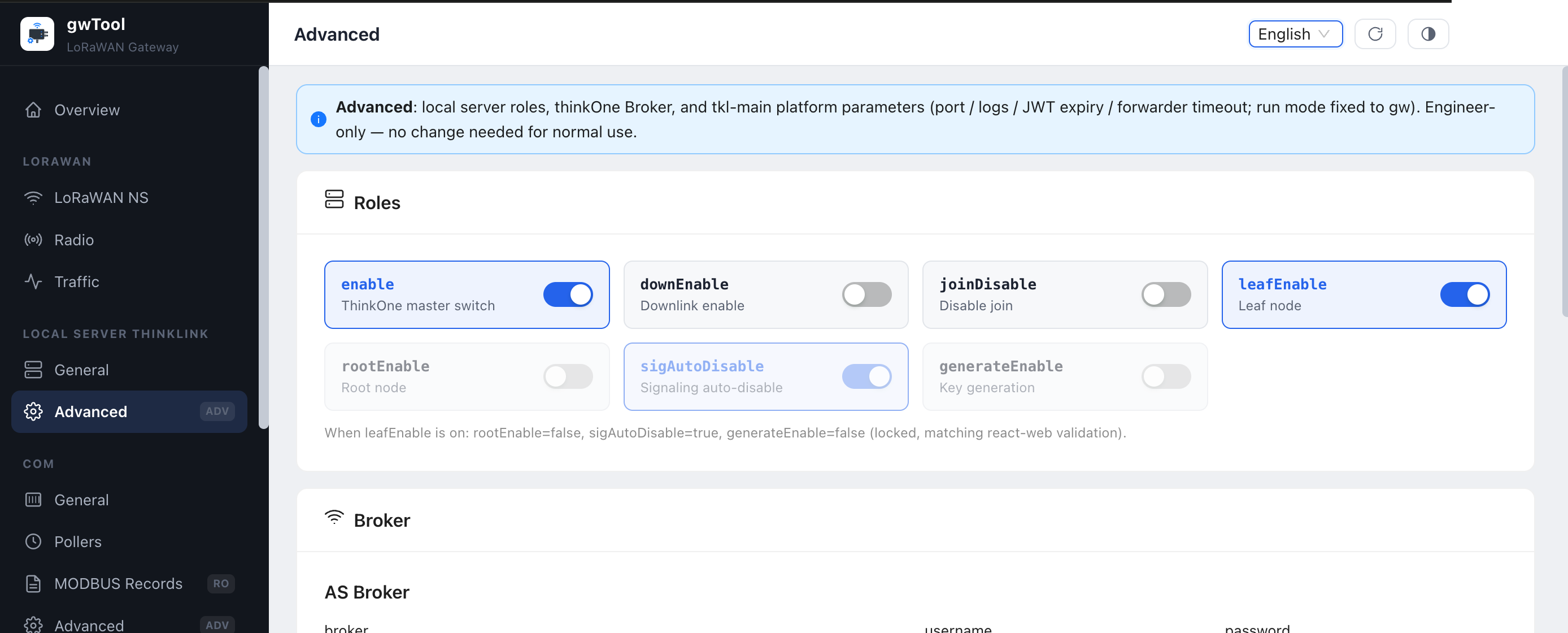
Figure 7: Role and Broker sections. Address, username, and password values are not shown.
Procedure and verification:
- Select leaf, root, downlink, automatic-disable, and key-generation roles according to the approved architecture.
- Enter the Broker address and account. When TLS is enabled, also verify the CA, client certificate, and client key.
- Save, restart only the service identified by the interface, and then verify the General page.
WARNING
Role combinations have dependencies. Do not override locked or mutually exclusive roles, and do not experiment with Broker credentials on a production gateway.
5. COM and Serial Services
5.1 COM General
Navigation: COM → General
Use this page to configure the serial-device path, baud rate, data bits, stop bits, and parity, and to inspect the gw-serial service state.
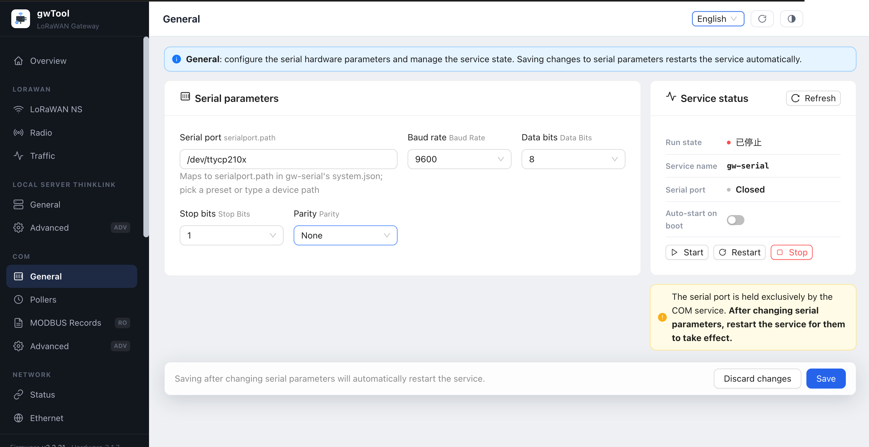
Figure 8: Serial parameters and service status. The service was stopped during capture; no start action was performed.
Procedure and verification:
- Obtain the serial path and communication settings from the connected-device documentation.
- Verify baud rate, data bits, stop bits, and parity before saving.
- Saving may restart the serial service. Refresh the status and confirm that the serial port opens and the service runs normally.
CAUTION
Mismatched settings cause timeouts, corrupt text, or invalid frames. Record the original settings and prevent multiple services from using the same port.
5.2 Pollers
Navigation: COM → Pollers
Use this page to manage scheduled tasks and Modbus pollers. A task may use a fixed interval or cron expression and may carry JSON parameters.
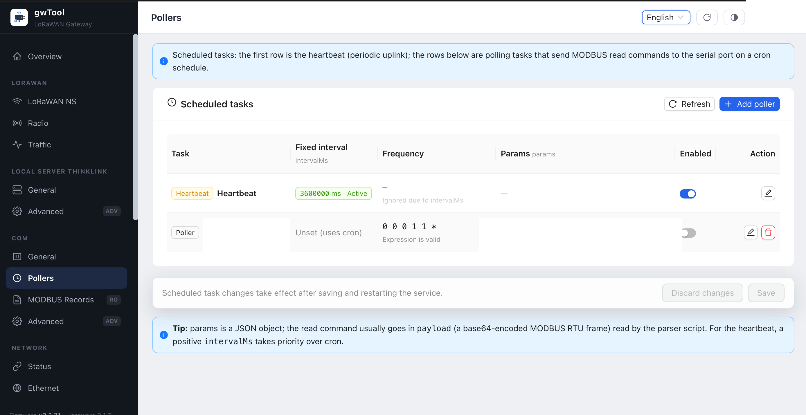
Figure 9: Heartbeat and poller list. The field task name and payload are masked.
Procedure and verification:
- Determine the slave address, function code, registers, and polling interval, and validate the request frame in a test environment.
- Add or edit a poller, then enter its task name, fixed interval or cron schedule, and JSON parameters.
- Save, confirm the enabled state, and inspect request and response frames in MODBUS Records.
WARNING
An excessively short interval can saturate the serial bus or overload the slave. Confirm dependencies before deleting, disabling, or modifying a task.
5.3 MODBUS Records
Navigation: COM → MODBUS Records
This read-only page displays the most recent cached serial requests and responses for diagnosing timeouts, exception responses, and protocol-setting errors.
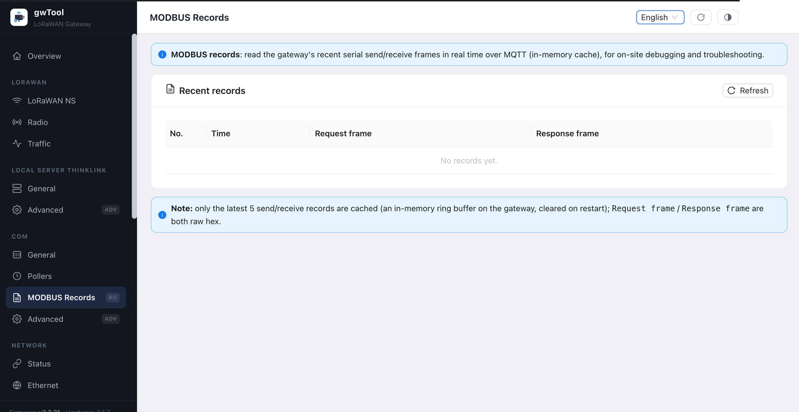
Figure 10: Page state when there are no recent records.
Procedure and verification:
- Confirm that the COM service and authorized poller are running.
- Refresh and match request and response frames by time.
- Record abnormal frames and compare them with the slave protocol. Only a small number of recent entries are retained, and a reboot may clear them.
5.4 COM Advanced
Navigation: COM → Advanced
Use this page to configure MQTT connectivity, serial timing, queue limits, logging, device attributes, and parser scripts.
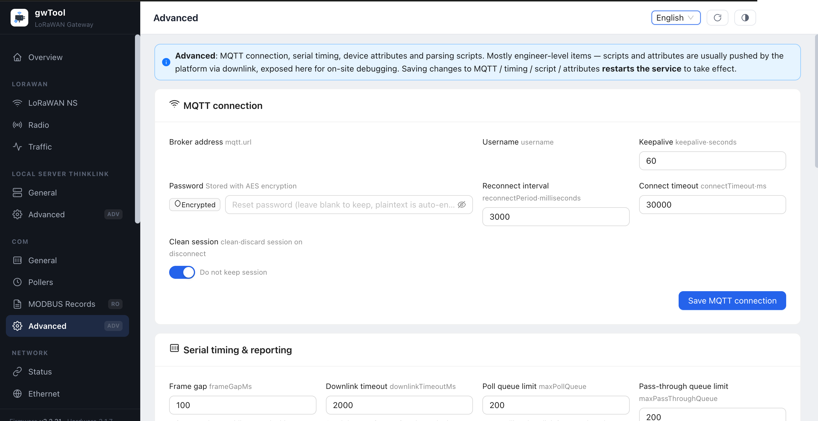
Figure 11: MQTT and serial-timing settings. Broker, username, and password values are masked.
Procedure and verification:
- Record the current Broker, reconnect interval, timeout, and queue parameters.
- When changing the MQTT address or account, also verify TLS, ACL, and upstream-service settings.
- Save timing, script, or attribute changes and wait for the service restart.
- Verify the service state, MODBUS records, and upstream Broker together.
WARNING
Advanced parameters and parser scripts can affect every serial workflow. Do not modify them without a rollback file and test results.
6. Network
6.1 Status
Navigation: NETWORK → Status
Purpose
The Status page summarizes Ethernet, Wi-Fi, and cellular connectivity, the active interfaces, and shortcuts to their configuration pages.
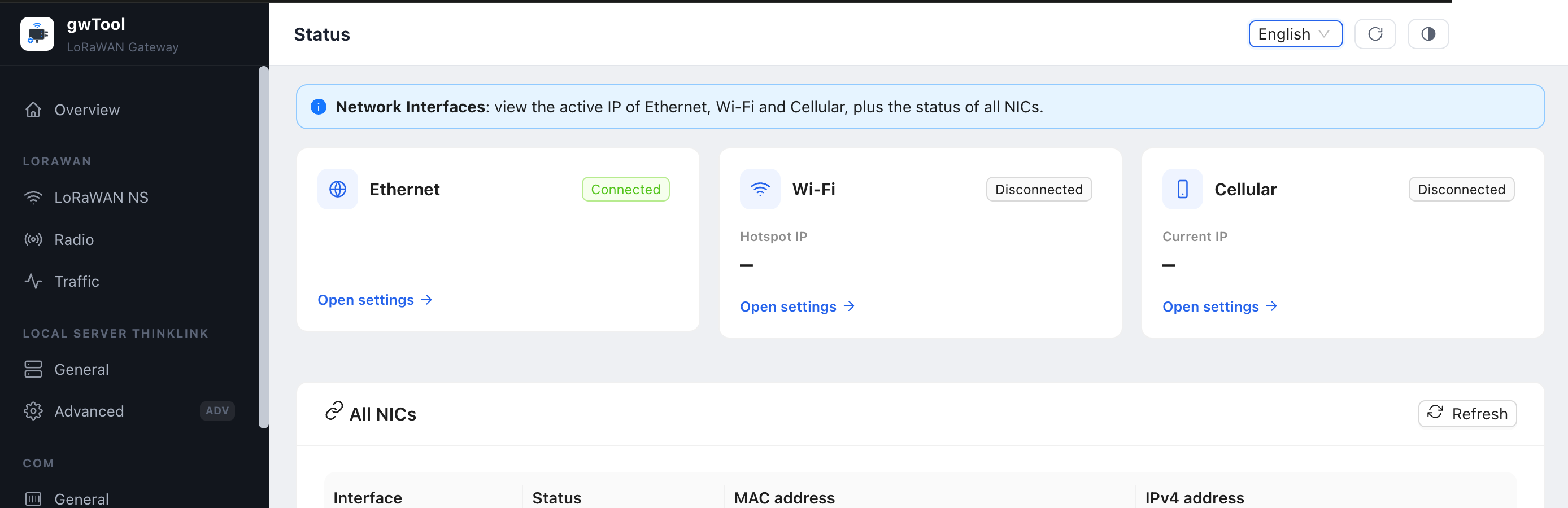
Figure 12: Link summary and network-interface table header. Active addresses and MAC addresses are not shown.
Key Fields and Controls
| Field or control | Description |
|---|---|
| Connected / Disconnected | Whether a link is currently established |
| Current IP / Hotspot IP | Active address; record or share it only when authorized |
| Open settings | Opens the corresponding network configuration page |
| All NICs | Lists interface name, state, MAC address, and IPv4 address |
| Refresh | Reads current state without changing configuration |
Procedure and Verification
- Check the three network cards and confirm that the intended link is connected.
- In All NICs, verify that the corresponding interface state is
UP. - Select Refresh and confirm that status updates normally.
- Open a configuration page only when that network type needs adjustment.
Troubleshooting
- If a card is disconnected, inspect cabling, signal, SIM service, and the upstream network before refreshing.
- If a card disagrees with the NIC table, wait several seconds and refresh; record the time and screenshot if the mismatch remains.
- If the active business path is uncertain, do not disable an interface. First confirm the primary link and site topology.
6.2 Ethernet
Navigation: NETWORK → Ethernet
Purpose
The Ethernet page enables or disables the wired interface and selects DHCP or static addressing.
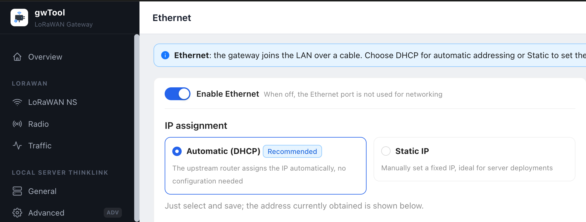
Figure 13: Ethernet enable control and address mode. Active site addresses are outside the cropped image.
Key Fields and Controls
| Field or control | Description |
|---|---|
| Enable Ethernet | Determines whether the wired interface participates in networking |
| Automatic (DHCP) | Obtains address, gateway, and DNS settings from an upstream server |
| Static IP | Manually specifies IP address, subnet mask, gateway, and DNS |
| Currently active | Shows settings that are actually in effect |
| Save | Applies the page changes and may interrupt the management session |
DHCP Configuration
- Confirm that DHCP is available on the upstream network.
- Keep Enable Ethernet on.
- Select Automatic (DHCP).
- Record the current management address and prepare to find the new address in the DHCP lease table.
- Save, reconnect to the management page, and verify Ethernet on the Status page.
Static Address Configuration
- Obtain an unused address, subnet mask, default gateway, and DNS setting from the network administrator.
- Select Static IP and complete all required fields.
- Verify that the address and gateway belong to a reachable network.
- Save, reconnect using the new address, and verify the Currently active section.
WARNING
Changing the management address, disabling Ethernet, or entering an incorrect gateway can immediately end the session. Prepare an alternate access path or on-site recovery assistance before remote changes.
6.3 Wi-Fi
Navigation: NETWORK → Wi-Fi
Use this page to select Hotspot (AP), Client, or Off mode and configure wireless security, NAT, and wired extension.
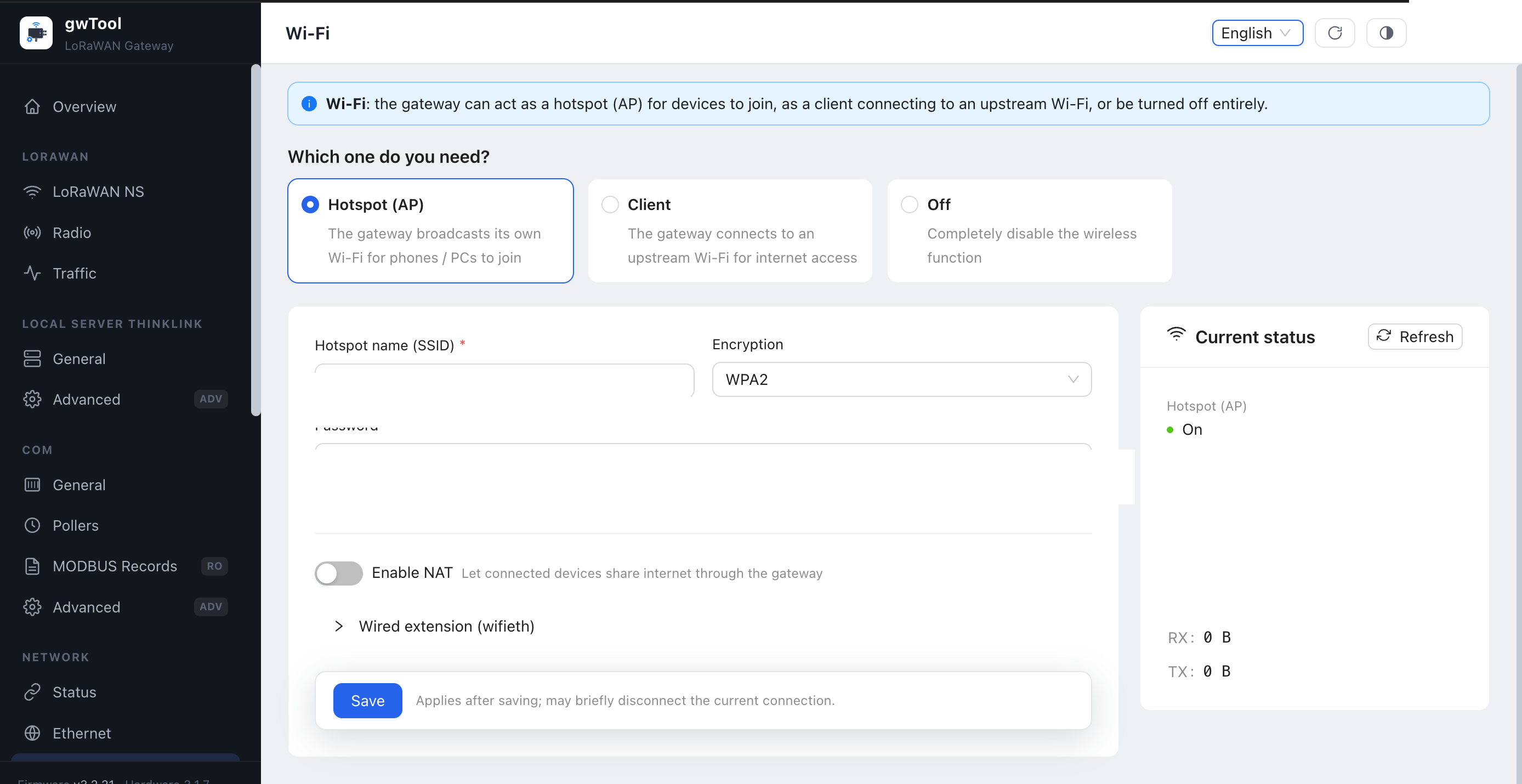
Figure 14: Hotspot mode. SSID, password, hotspot address, and MAC information are masked.
Mode summary:
- Hotspot (AP): the gateway publishes a wireless network for local devices.
- Client: the gateway connects to upstream Wi-Fi; verify SSID, BSSID, signal, and encryption.
- Off: disables both hotspot and client operation.
- NAT and wired extension: control traffic forwarding and DHCP or static addressing according to the site topology.
Procedure and verification:
- Preserve a working wired management path and record the current settings.
- Select the mode and enter the SSID, encryption, and password. An open network is not recommended for production.
- Configure NAT and wired extension if required, read the disconnection warning, and save.
- Reconnect through the backup path, refresh, and verify mode, interface state, address, and traffic counters.
WARNING
Changing mode, SSID, key, NAT, or address can immediately end the session. If access is lost, use the alternate wired path to restore the previous settings.
6.4 Bluetooth
Navigation: NETWORK → Bluetooth
Use this page to inspect the Bluetooth worker, advertisement and backend-connection states, and recent command logs.
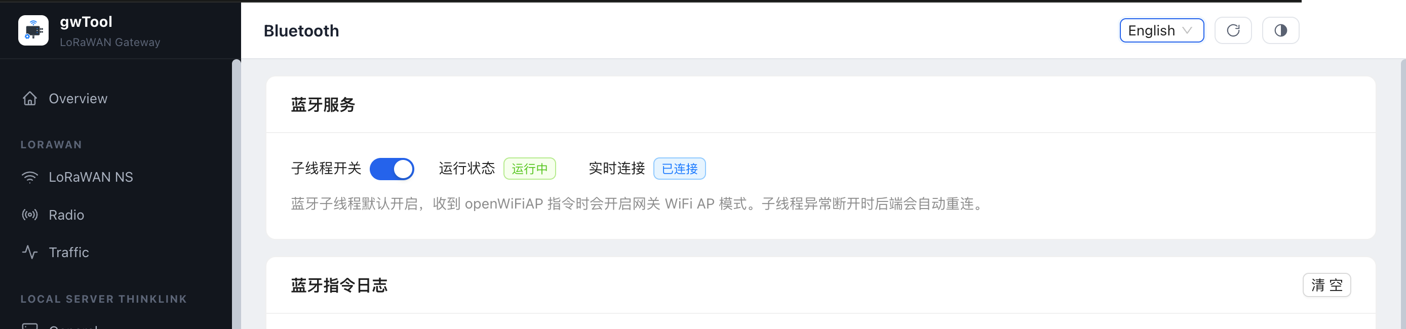
Figure 15: Bluetooth service area. Log entries are cropped out to avoid exposing the advertisement identifier.
Procedure and verification:
- Check whether the worker is running and whether the live connection matches expectations.
- Inspect recent logs only when troubleshooting, and redact device identifiers before sharing a screenshot.
- Record state and logs before an authorized engineer investigates the adapter and backend service.
CAUTION
Toggling the Bluetooth worker changes device-access capability. Do not switch it without confirming the business impact.
6.5 Cellular
Navigation: NETWORK → Cellular
Use this page to enable 4G/LTE dialing, enter an APN, inspect SIM and signal status, and test cellular-path connectivity.
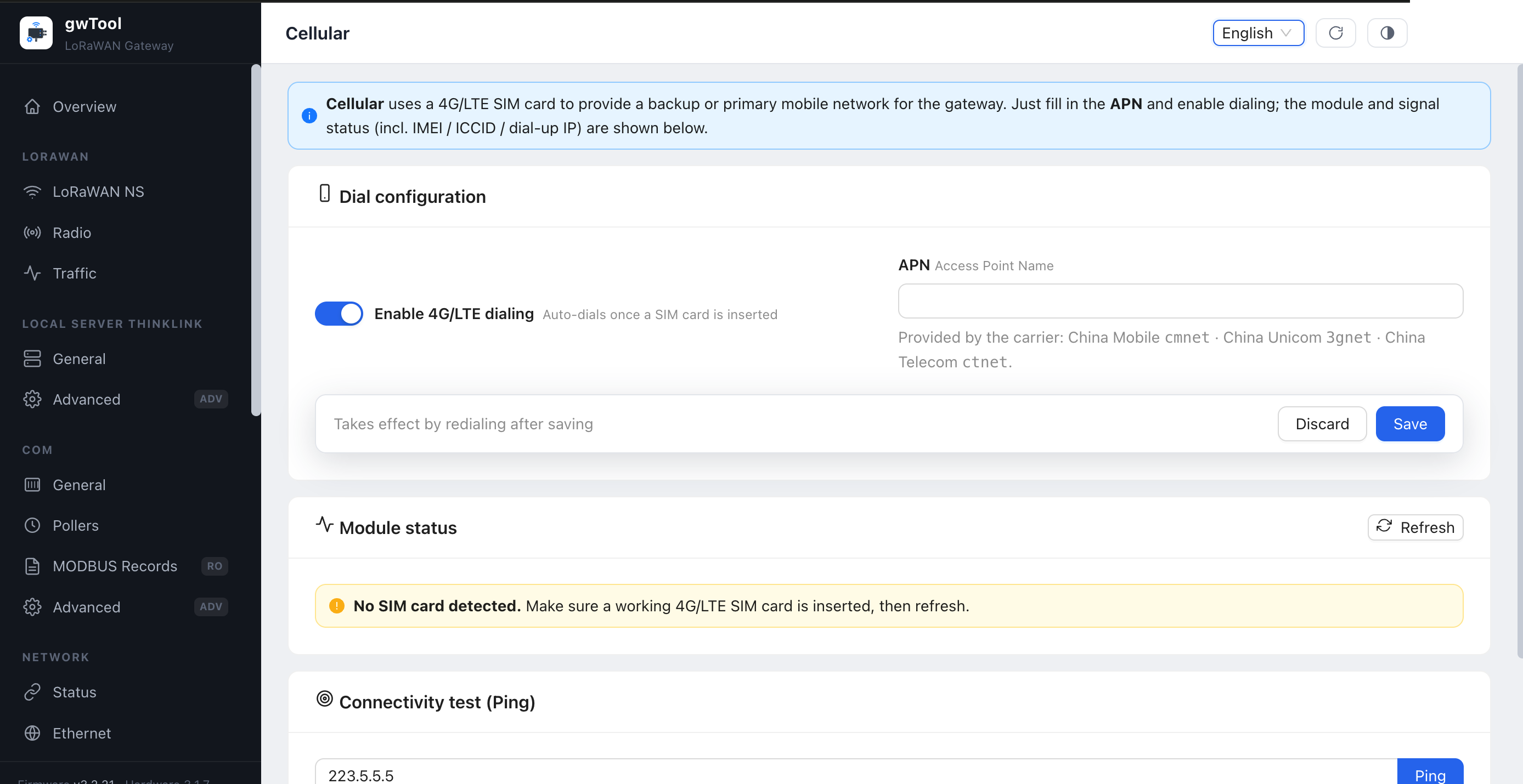
Figure 16: Cellular configuration and Ping area when no SIM card is detected.
Procedure and verification:
- Power down or follow the device procedure before installing a valid SIM, then refresh the module state.
- Enter the carrier-approved APN, enable dialing, and save.
- Wait for redial and verify signal, carrier, assigned address, and interface state.
- Ping only an approved target to confirm public or private-network reachability.
IMPORTANT
IMEI, ICCID, phone number, APN, and assigned address are sensitive. Redact them from tickets and screenshots.
6.6 Network Advanced
Navigation: NETWORK → Advanced
Use this page to manage OpenVPN files and state, the netCheck connectivity watchdog, and outbound-link selection.
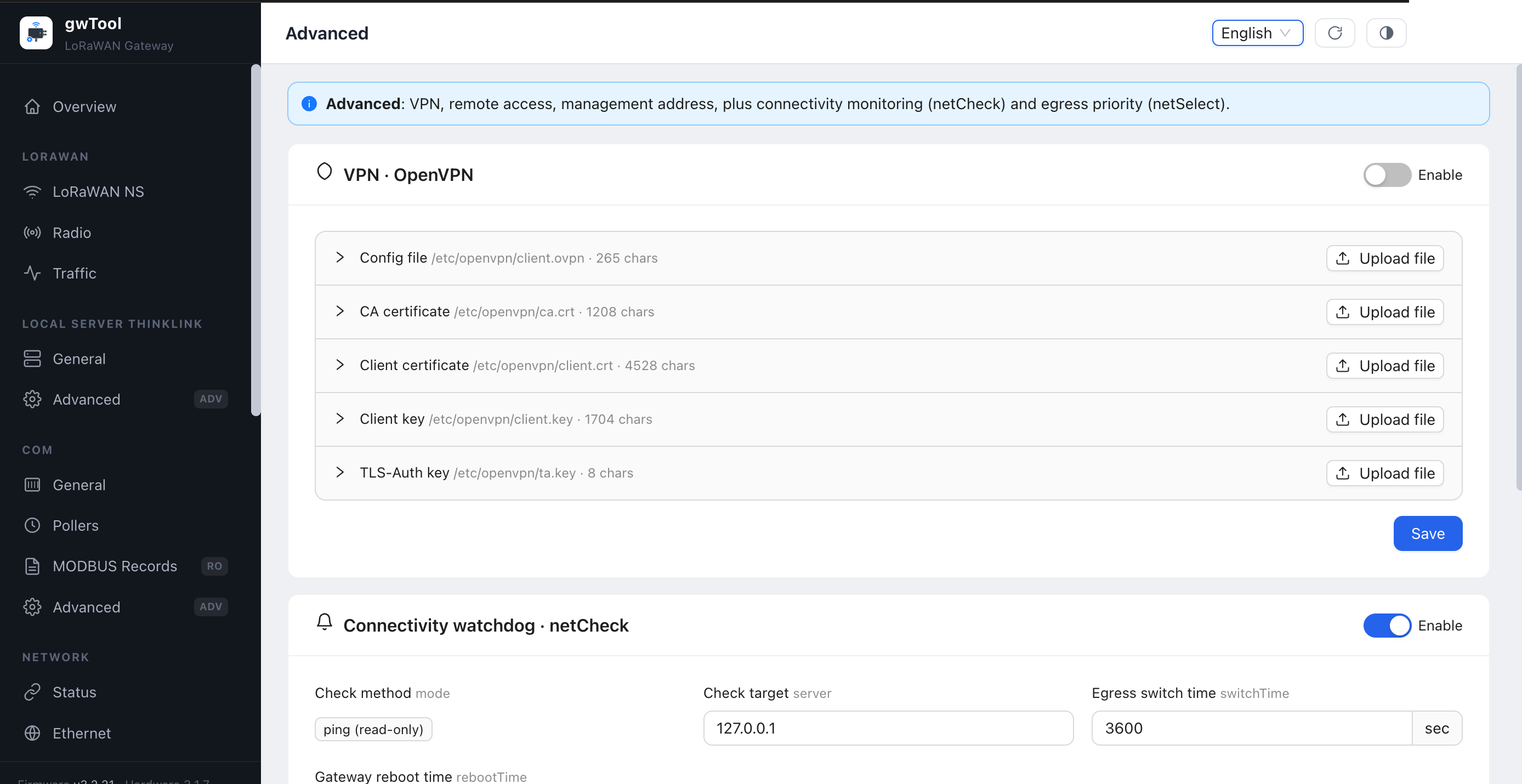
Figure 17: OpenVPN file controls and netCheck settings. Certificate contents are not expanded.
Procedure and verification:
- For OpenVPN, confirm that the configuration, CA, client certificate, client key, and TLS-Auth key belong together.
- Verify each uploaded file and its approved source before enabling VPN during a maintenance window.
- For netCheck, select a stable reachable target and reasonable failover and reboot thresholds.
- Save and verify management access, the VPN tunnel, and outbound routing; do not rely only on a switch state.
WARNING
VPN keys and certificates must not appear in screenshots or tickets. Incorrect routes, probe targets, or thresholds may cause repeated failover or reboot.
7. System
7.1 Device
Navigation: SYSTEM → Device
Use this page to inspect device identity and versions, configure time and time zone, and back up or restore configuration.
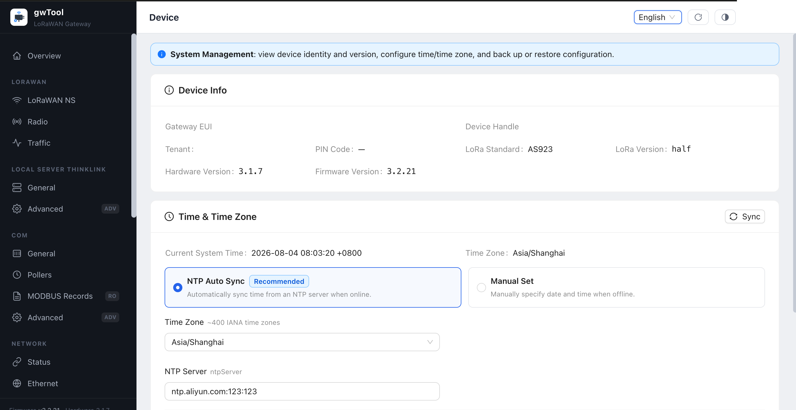
Figure 18: Device information and time settings. Gateway EUI, tenant, and device handle are masked.
Procedure and verification:
- Record firmware, hardware, LoRa version, and time zone before support escalation or upgrade.
- Prefer NTP Auto Sync on connected gateways and use a reachable, trusted NTP server.
- Use manual time only when offline, and verify the time zone at the same time.
- After synchronizing or saving, reload and compare the system time with a trusted reference.
CAUTION
Incorrect time affects certificates, logs, scheduled tasks, and data timestamps. Before restoring a backup, confirm its source, gateway model, and firmware compatibility.
7.2 Account & Security
Navigation: SYSTEM → Account & Security
Use this page to change the web administrator password.
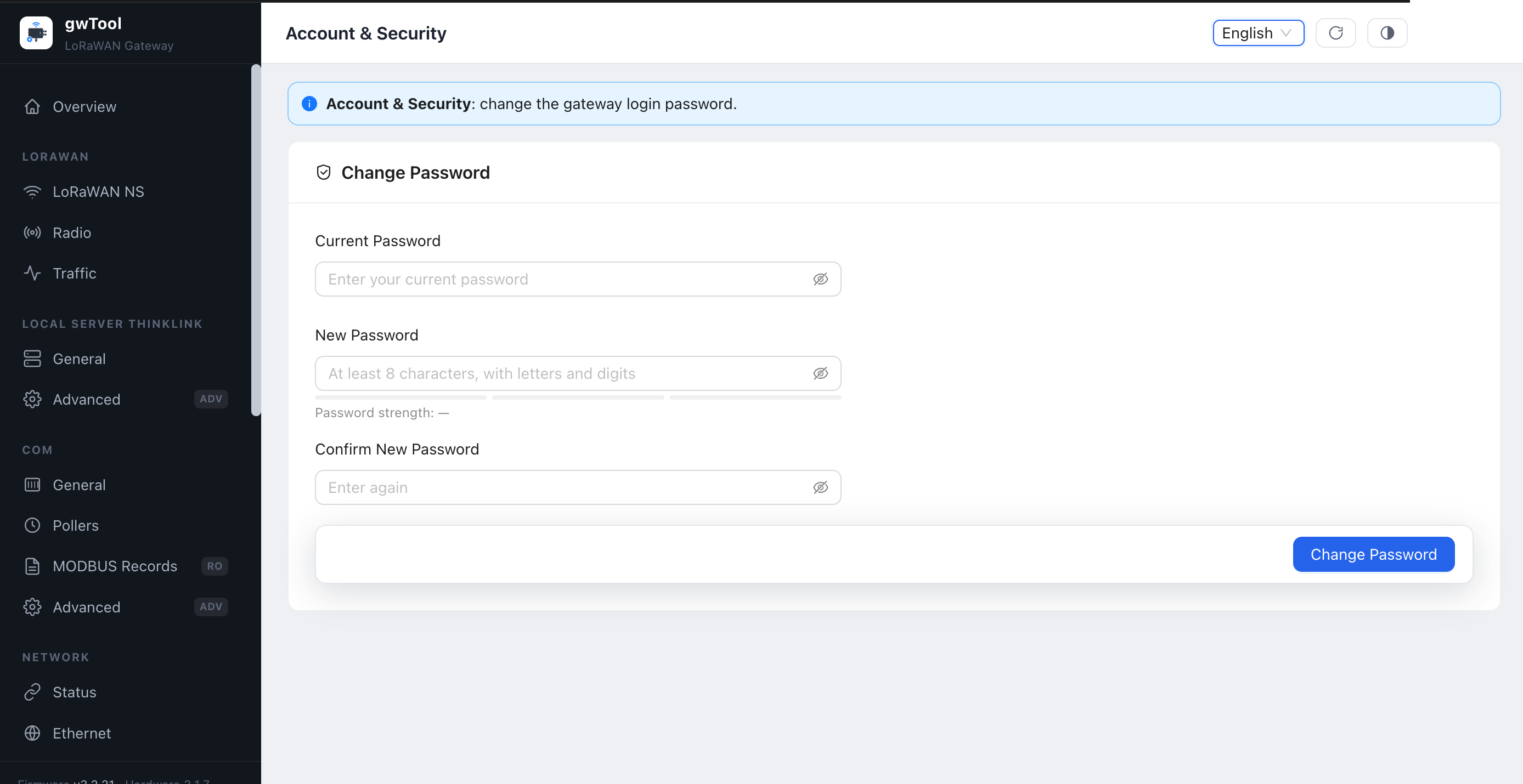
Figure 19: Password-change form with all fields empty.
Procedure and verification:
- Enter the current password and then enter and confirm a new password that meets policy.
- Before submitting, store the new password in the approved password manager.
- Sign out after the change and sign in again with the new password.
WARNING
Do not reuse a default or shared password. If sign-in fails after a change, follow the approved account-recovery procedure instead of guessing repeatedly.
8. Upgrade
Before any upgrade, verify product and hardware compatibility, the package source and checksum, export the configuration, ensure stable power and management access, and schedule business downtime.
8.1 ThinkLink Upgrade
Navigation: UPGRADE → ThinkLink Upgrade
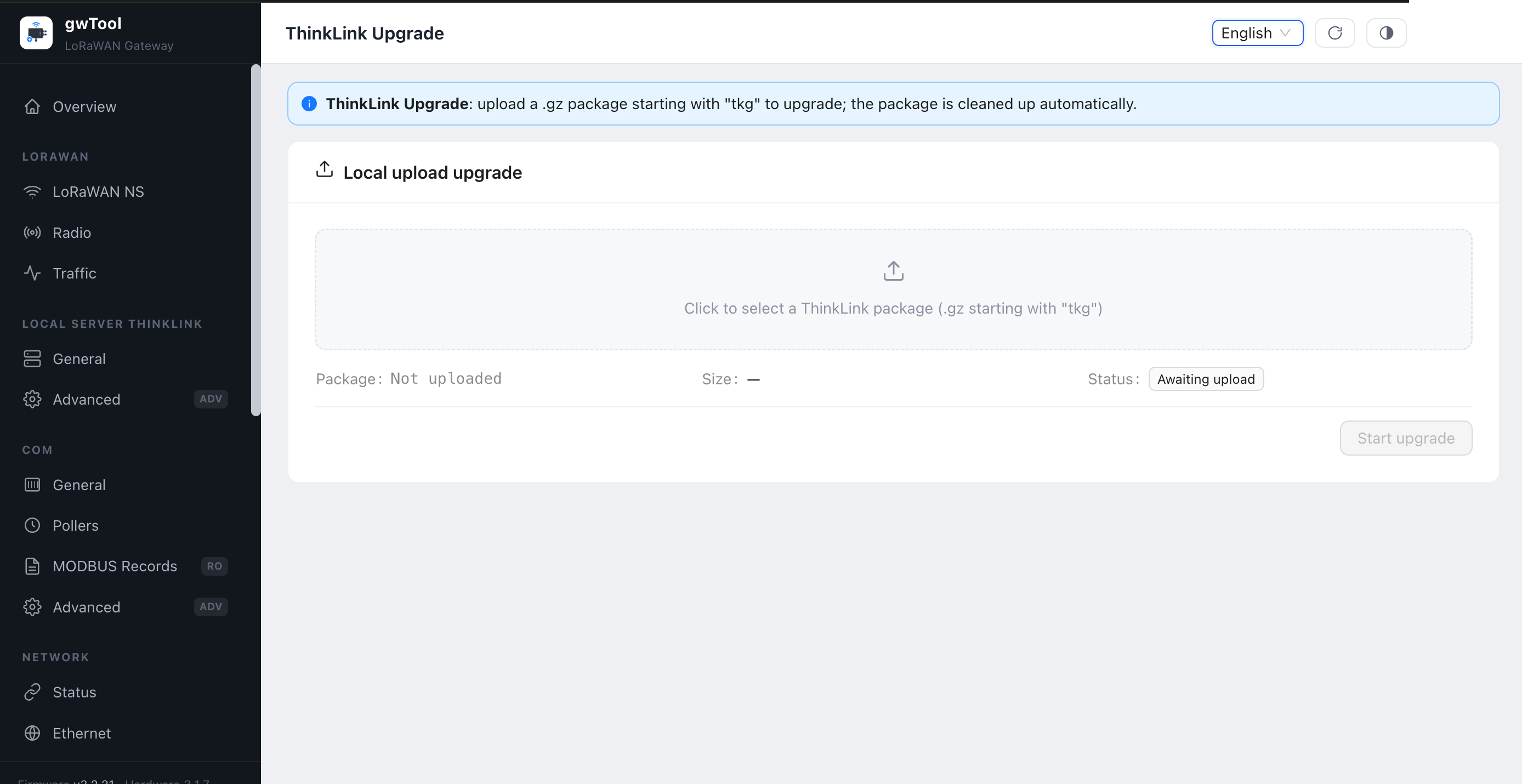
Figure 20: Safe initial state before selecting an upgrade package.
Select an approved .gz ThinkLink package whose filename begins with tkg. Verify the name and size before starting. After completion, sign in again and check ThinkLink General and the required services.
8.2 GwSerial Upgrade
Navigation: UPGRADE → GwSerial Upgrade
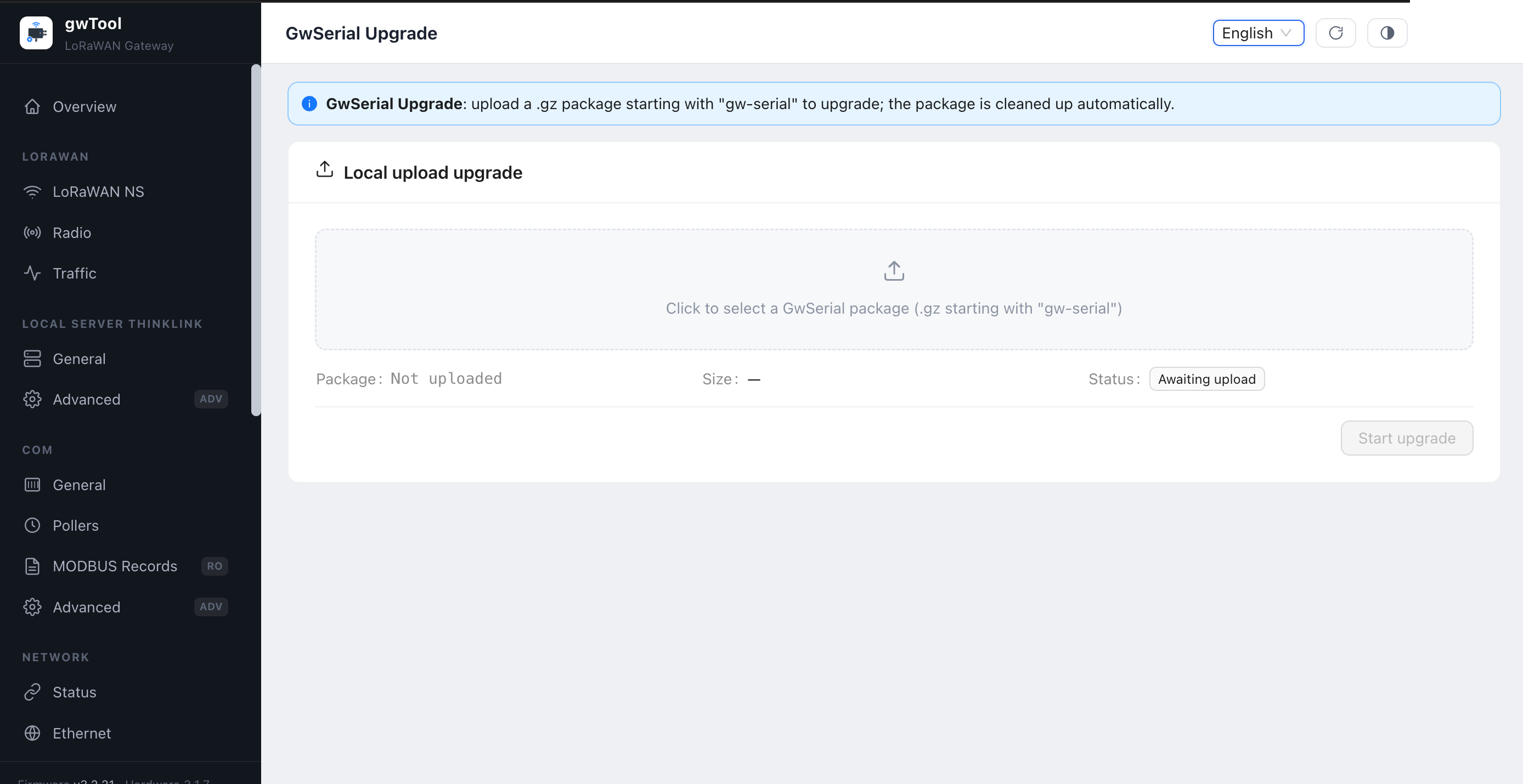
Figure 21: GwSerial package selector with no file uploaded.
Select an approved .gz package whose filename begins with gw-serial. After upgrading, verify COM service state, serial-port availability, pollers, and records.
8.3 GwTool Upgrade
Navigation: UPGRADE → GwTool Upgrade
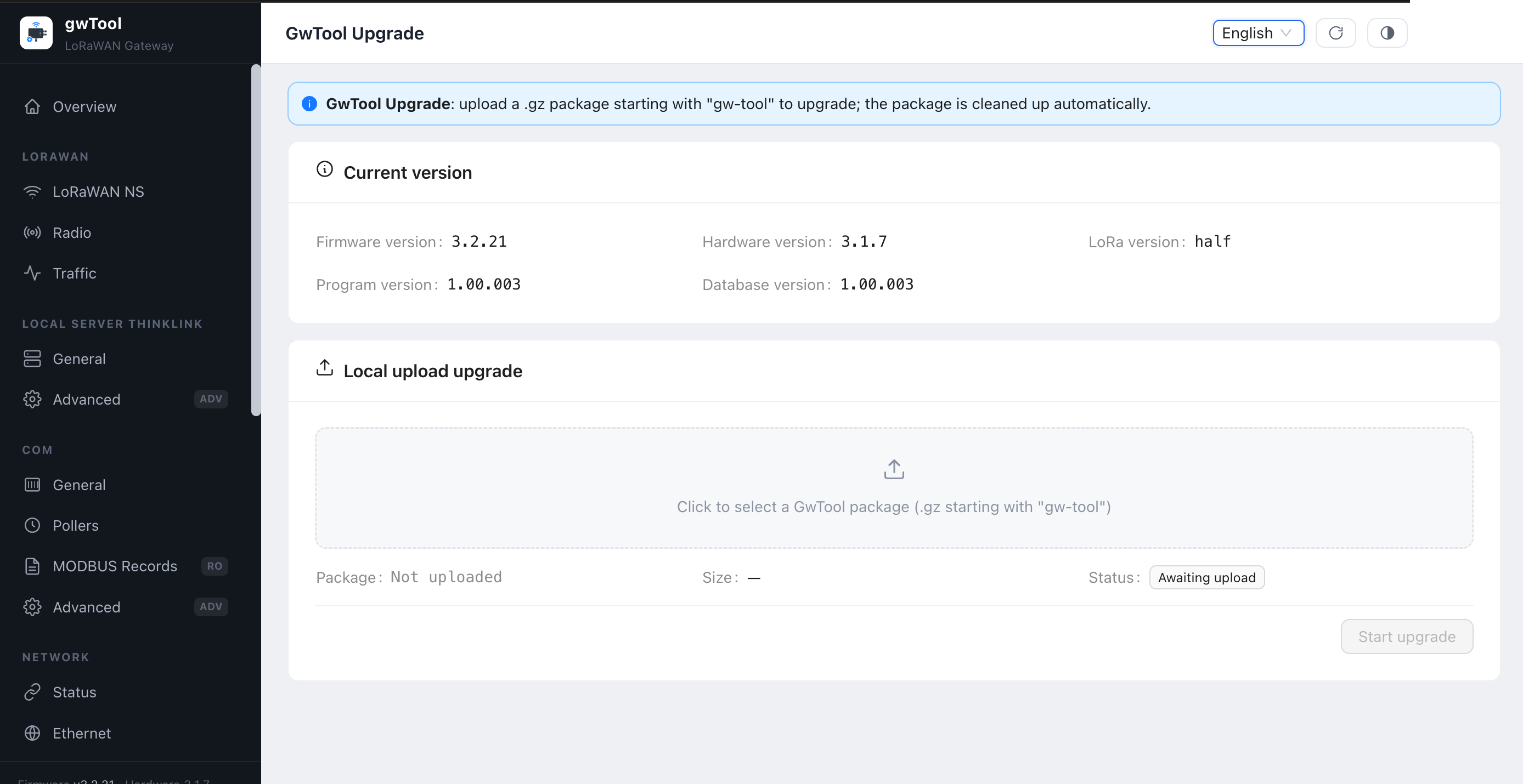
Figure 22: Current version and GwTool package selector.
Select an approved .gz package whose filename begins with gw-tool. Record firmware, hardware, application, and database versions first; after upgrading, force-refresh the browser and sample the core configuration pages.
8.4 Firmware Upgrade
Navigation: UPGRADE → Firmware Upgrade
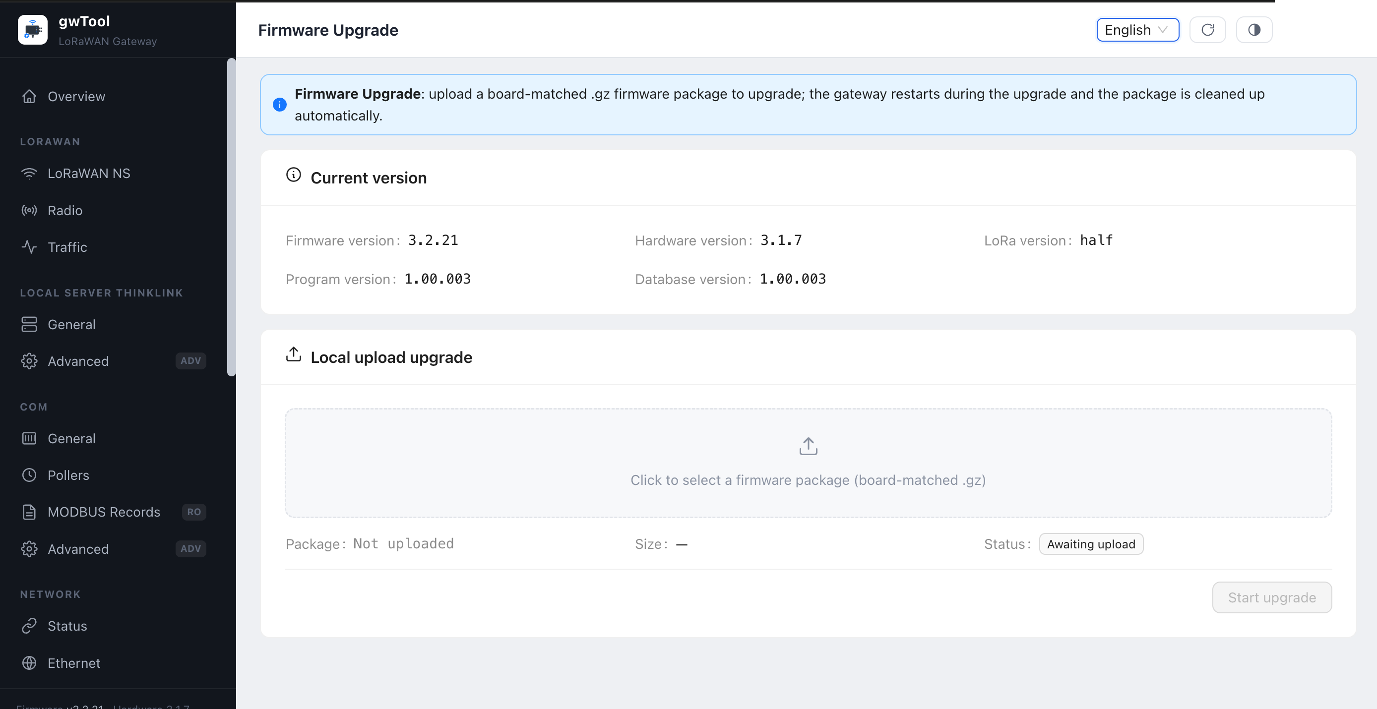
Figure 23: Firmware version and package selector.
Use only an approved .gz firmware package named for the target board. The gateway reboots during firmware upgrade. Do not remove power, close the page, or change networks; after recovery, verify version, network, LoRaWAN, ThinkLink, and COM operation.
WARNING
The four package types are not interchangeable. Do not upload packages with an unknown source, failed checksum, or mismatched model. Stop repeated attempts after a failure and retain the logs.
9. Maintenance
9.1 Self-check
Navigation: MAINTENANCE → Self-check
Self-check evaluates system resources, service state, business health, and network links, and groups results as pass, attention, failure, or information.
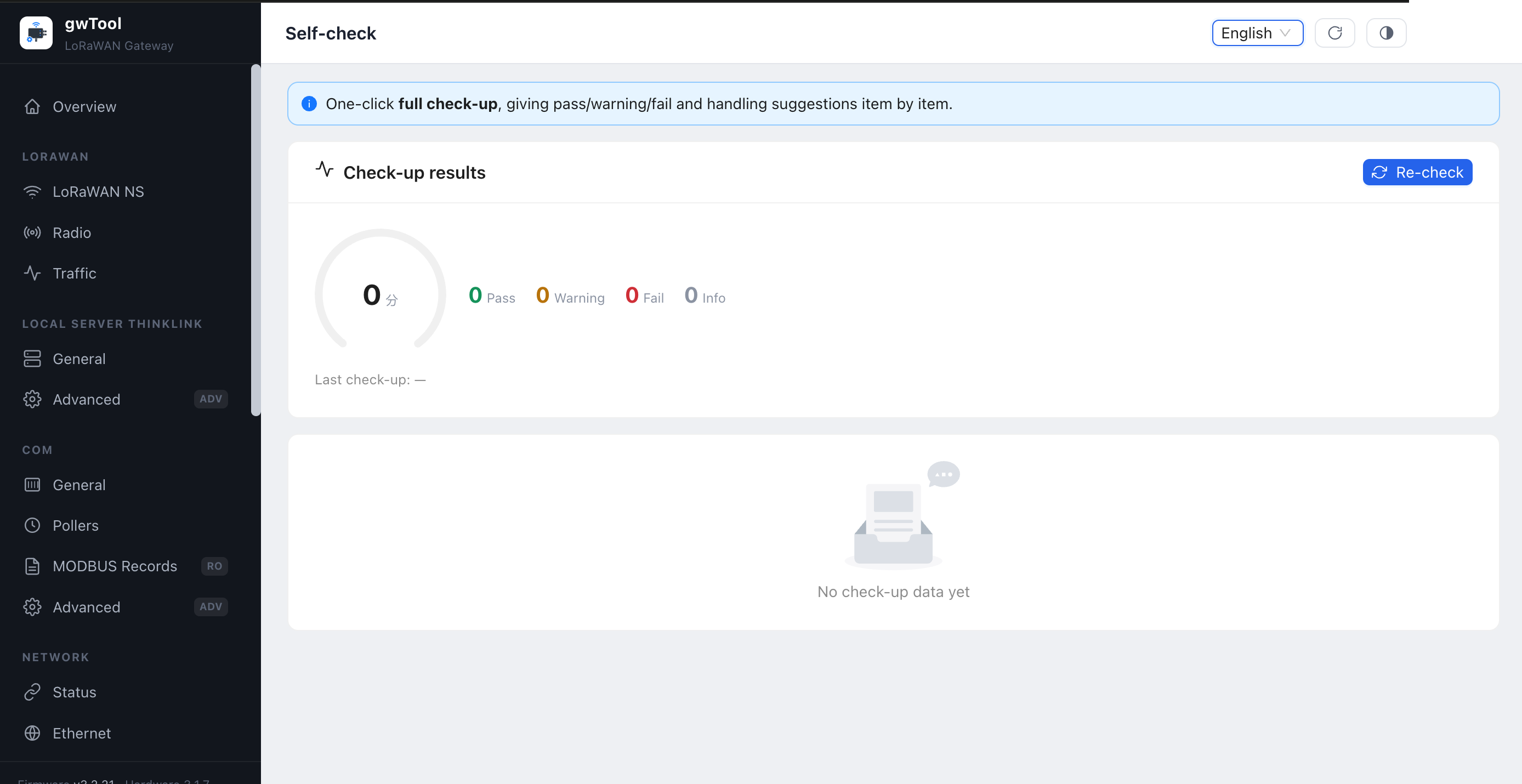
Figure 24: Initial state before a health check. The capture did not trigger the self-check action.
Procedure and verification: Run the check only when business conditions permit, wait for every group to complete, resolve failures before attention items, and retain only redacted results. A passing self-check does not replace end-to-end traffic and platform verification.
9.2 System Logs
Navigation: MAINTENANCE → Logs
Use the log viewer to select a file, read from the tail or head, filter by keyword, control live refresh, and download logs.
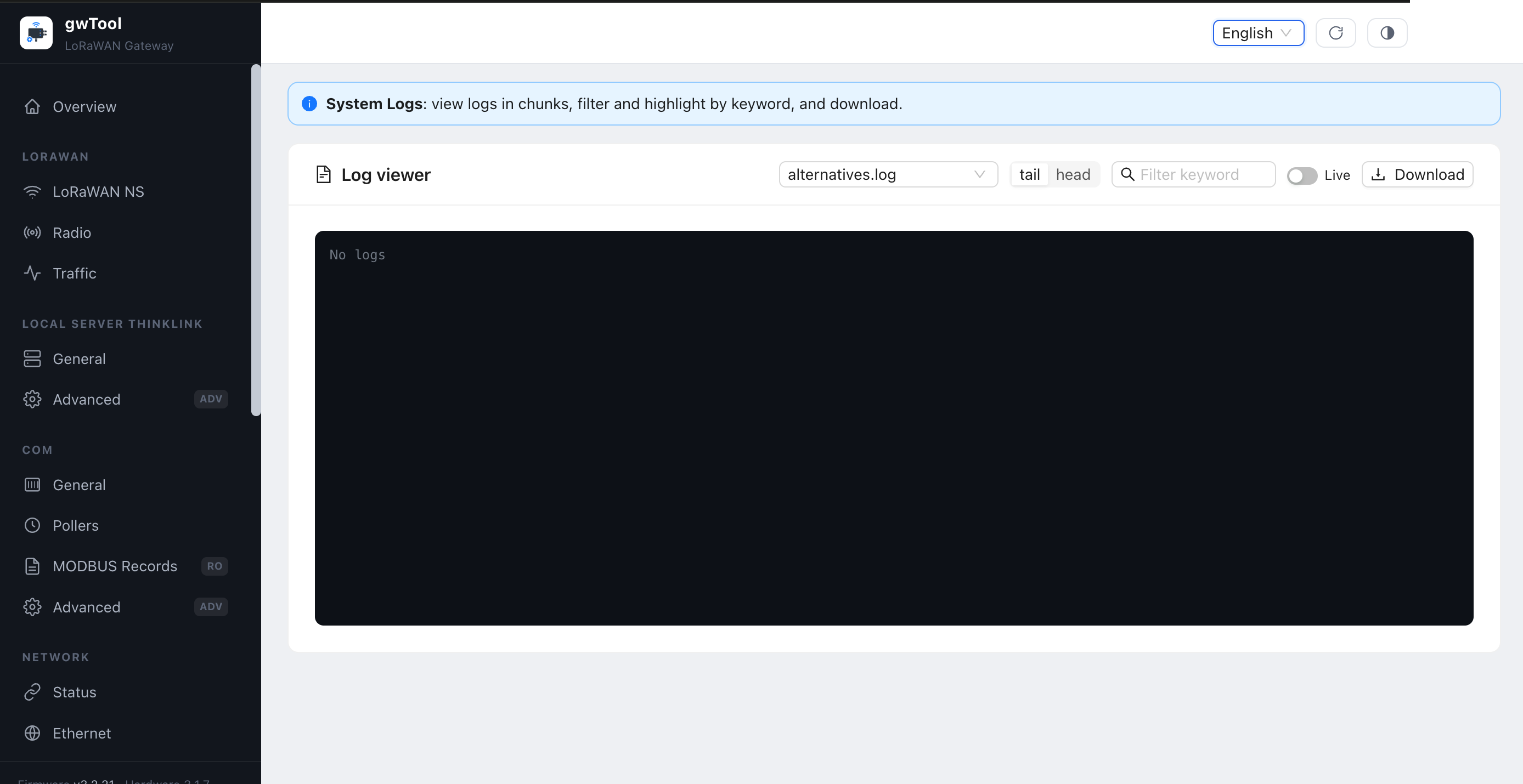
Figure 25: Log viewer with no displayed entries.
Procedure and verification: Select the log for the affected module, start from tail for recent events, filter by time and error keyword, and download only when offline analysis is required. Turn off Live before leaving the page.
IMPORTANT
Logs may contain addresses, device identifiers, accounts, or business data. Review and redact them before downloading or sharing.
9.3 Terminal
Navigation: MAINTENANCE → Terminal
The page provides an authenticated WebSocket terminal to the gateway SSH service for separately authorized diagnostics.
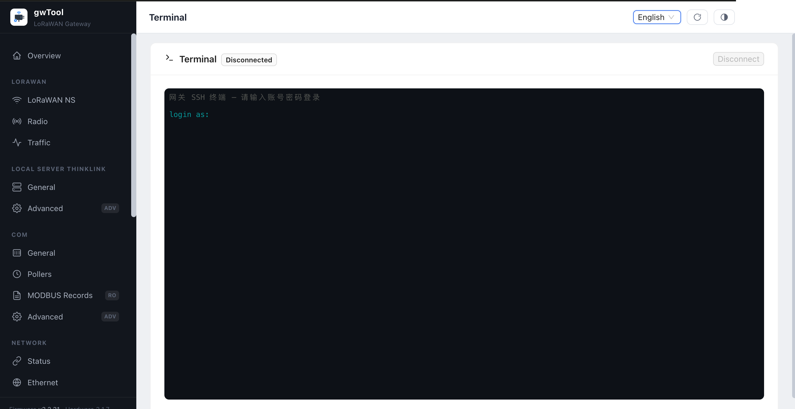
Figure 26: Terminal sign-in prompt. No username, password, or command was entered during capture.
Controlled use:
- Obtain change authorization and define permitted read-only commands, recording requirements, and exit conditions.
- Confirm the target device identity after signing in and perform only the minimum necessary checks.
- Record only required output, disconnect explicitly, and close the page when finished.
WARNING
Terminal access can bypass web-interface safeguards. This manual does not authorize shell operations, service control, or device control; execute only commands approved under a separate procedure.
9.4 Services and Gateway Reboot
Navigation: MAINTENANCE → Services
Purpose
The Services page shows service state, auto-start setting, and uptime. It also provides per-service controls, full-gateway reboot, and an automatic reboot schedule. The screenshot focuses on the highest-risk reboot area.
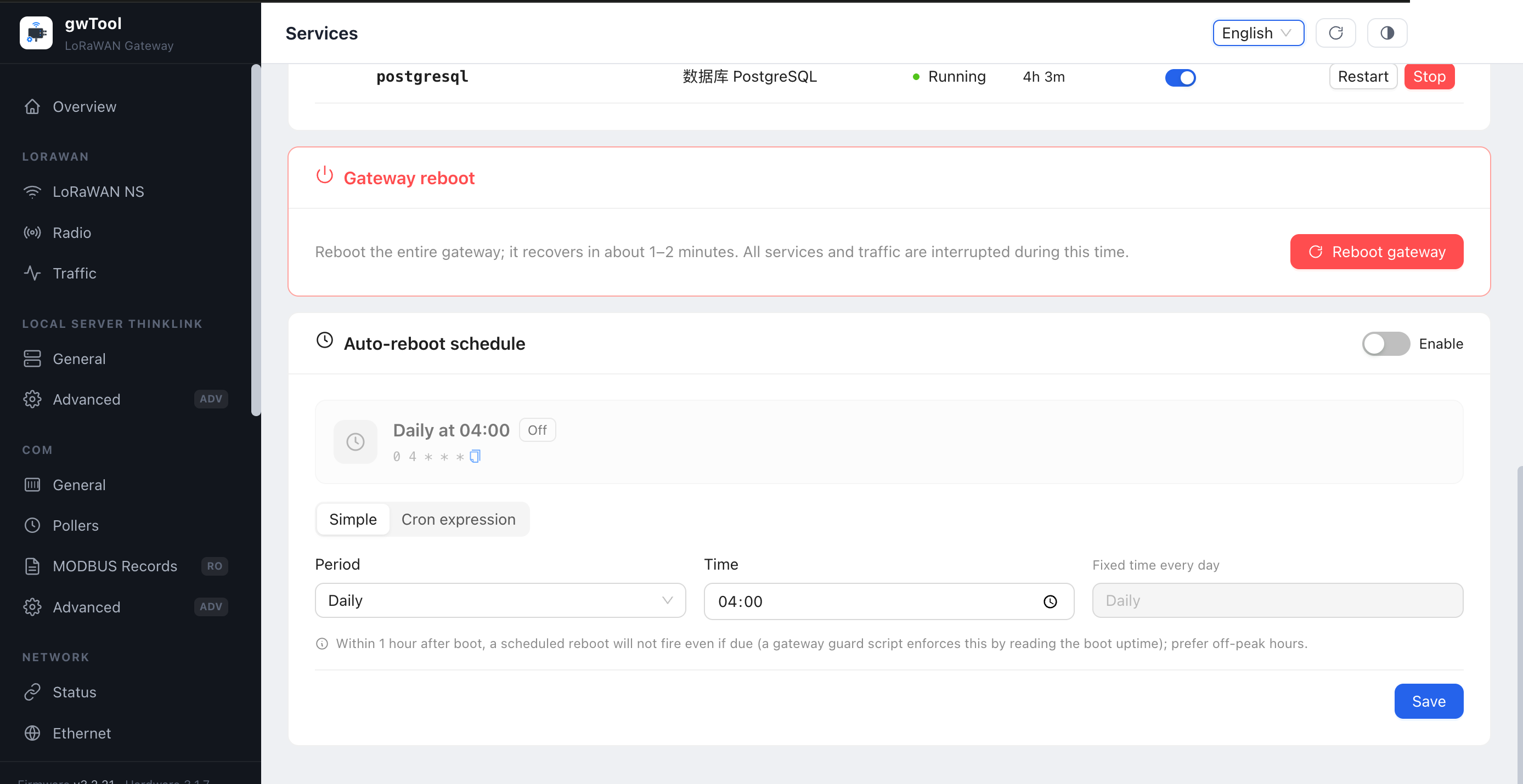
Figure 27: Gateway reboot and automatic reboot schedule. No reboot or save action was performed during capture.
Service Status Check
- Review service Status and Uptime.
- Record the name, state, uptime, and observation time for an abnormal service.
- Use Refresh to rule out a transient display state.
- Do not change auto-start or start, stop, or restart a service before confirming dependencies.
Manual Gateway Reboot
- Notify stakeholders and schedule at least a 1–2 minute interruption window.
- Confirm that no upgrade, configuration write, or critical data transfer is in progress.
- Record the current management address and critical-service states.
- Select Reboot gateway and follow the confirmation prompt.
- Wait for recovery, sign in again, and verify Overview, network status, and critical services.
Automatic Reboot Schedule
- Enable determines whether the schedule is active.
- Simple generates a schedule from period and time; Cron expression is intended for administrators familiar with cron.
- The page states that a scheduled reboot is suppressed during the first hour after boot.
- Select an off-peak time and verify the gateway time zone before saving.
CAUTION
Reboot interrupts all services and traffic. An incorrect schedule can create recurring outages; verify recovery at the next approved schedule window.
Verification and Recovery
- After a manual reboot, wait for the gateway to recover, sign in, and check Overview, network, and service status.
- After saving a schedule, reopen the page and verify enabled state, displayed time, and cron expression.
- If the gateway does not return, inspect power and connectivity and follow the site recovery procedure. Do not issue repeated reboot requests.
10. General Safety and Recovery
- Record current values and firmware versions before changes, and retain an approved configuration backup when appropriate.
- Change one functional area at a time and verify the result immediately after saving.
- Schedule network, service, upgrade, and reboot work in a maintenance window with a tested rollback path.
- A fault record should include time, page, before-and-after state, and actions already taken. Exclude passwords, tokens, and unique device identifiers.
- If the interface differs from this manual, treat the current formal interface and version-specific documentation as authoritative. Stop uncertain high-risk work and escalate for confirmation.
Revision: 2026-08-04. English administrator manual 1.0 covers the sign-in page and all 26 formal application pages.