KC11 DIN-Rail RS-485 Data Logger
1. Product Introduction

2. Product Description
KC11 is a high-performance, low-power, highly configurable data transmission unit (DTU) independently developed by ManThink . Product Integration High Performance MCU and LoRa ® RF chip, based on LoRa ® Wireless technology, supports standard LoRaWAN ® Protocol, which has the advantages of long communication distance, strong signal penetration and low power consumption.
KC11 adopts industrial-grade guide rail design, supports 100V-230V AC wide voltage power supply, and is suitable for all kinds of industrial field environment. Through the RS-485 interface, external devices can be easily connected, data collection and remote control can be realized, and business data can be stably uploaded to the application platform through the LoRaWAN network.
The product is compatible with ManThink and third-party LoRaWAN ® The Gateway also supports access to IoT platforms such as ThinkLink, ChirpStack, and The Things Network(TTN). It has excellent system integration capabilities.
KC11 has a built-in EB virtual machine, which supports the generation of firmware through EB script compilation and remote deployment through FUOTA (Firmware Over-the-air upgrade). With the help of EB virtual machine, users can flexibly realize protocol analysis and docking of RS-485 equipment, and complete core business logic processing such as COV (change value reporting), alarm triggering, data reorganization, etc. on the terminal side, thus significantly improving the response efficiency and intelligence level of the system.
3. Application areas
- Industrial Site
- Electric meter reading
- Hydrometeorological monitoring
- Environmental protection, municipal and other related scene monitoring
4. Main features
- Support RS-485 interface
- AC 85V-270V power supply
- Support for EB virtual machines
- Support remote upgrade via LoRaWAN communication
- Support ThinkLink/ChirpStack/TTN platform docking
- Support US902,AU915,AS923,EU868,EU433,CN470 LoRaWAN standards
- Compatible with all RS-485-based communication protocols
5. Parameters
| Interface | joint Type | 2.54mm Terminal |
|---|---|---|
| wiring quantity | 4 | |
| display | 4 indicator lights, RU,LR,TX,RX |
| Item | Value |
|---|---|
| § Wireless Parameters | |
| Protocol | standard LoRaWAN |
| regional Standards | CN470/EU433/EU868/AS923/AU915/Us902 |
| transmit power | maximum Support 22dBm ( can be changed) |
| receiving sensitivity | -142dBm(SF=12,BW=125kHz) |
| Working mode | OTAA/ABP Class C |
| § Configuration | |
| test /Trigger mode | press the button 2 seconds to trigger heartbeat data > 6 seconds to trigger the network |
| parameter configuration | by NS issue instruction |
| § Physical Characteristics | |
| power supply mode | AC 85V-270V |
| receiving current | <8mA |
| emission current | <110mA (22dBm transmit power) |
| working temperature | -40°C ~85°C |
| relative humidity | ≤ 95% (no condensation) |
| protection level | IP53 |
| Material &Color | ABS + PC, White |
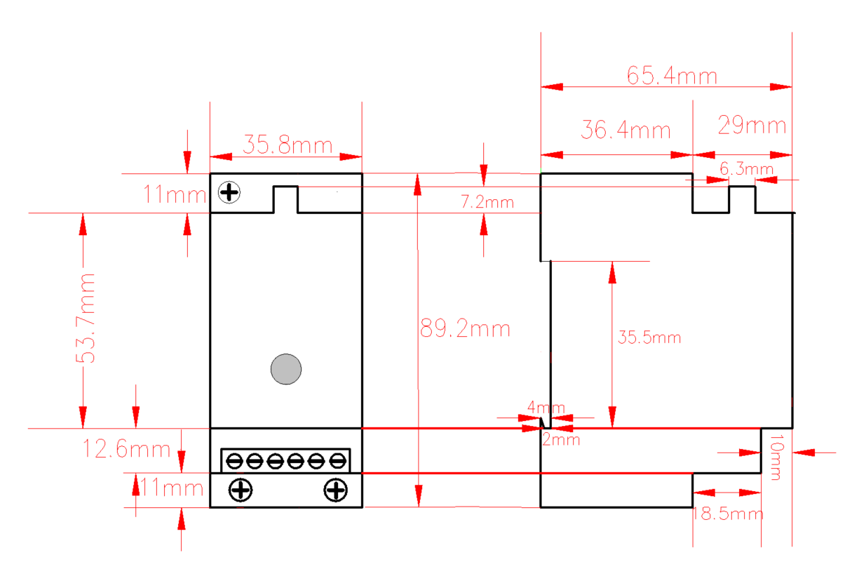
| dimensions | 89.2mm x 35.8mm x 65.4mm |
| installation method | DIN rail |
6. Dimensions and Interfaces
6.1 DIimensions
6.2 Interface Definition
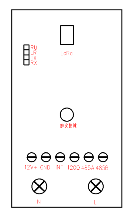
| Name | Definition |
|---|---|
| N | 80-270V AC power supply zero line |
| L | 80-270V AC power supply live wire |
| 485A | 485A |
| 485B | 485B |
| 120Ω; | matching resistor, bus equipment is more, the distance is far, when there is interference, this terminal and RS485A short circuit |
| INT | I/O input |
| GND | GND |
| 12V + | keep interface, please keep hanging |
| trigger button | click this button, KC11 will query the data and upload |
| long press the button for more than 6 seconds, will trigger the network | |
| RU | The system operation indicator flashes once per second, indicating that the system is operating normally |
| LR | status indicator, flashing for 100ms when data is sent and received |
| TX | data transmission indicator, send flashing while RS-485 data |
| RX | data reception indicator, blinking when receiving RS-485 data |
7. Product Model
7.1 Model example
KC118-A1-AS923-N
7.2 Model component breakdown
KC118: product series and RF band.KC11identifies a second-generation DIN-rail RS-485 DTU.8identifies the 800 MHz-and-above RF version for EU868, AS923, AU915 and US902.- Other band option:
4identifies the 400 MHz RF version for EU433 and CN470.
-A1: hardware and power configuration.Aidentifies the default hardware configuration.1identifies an AC 85–270 V power input.
-AS923: LoRaWAN regional standard.AS923means that the device supports the LoRaWAN AS923 regional parameters.- Other regional codes are
CN470,EU433,EU868,AU915andUS902;US902denotes the LoRaWAN US915 (902–928 MHz) regional parameters.
-N: default version.Nidentifies the default version.- Other values are reserved for customized or special versions.
7.3 Complete model meaning
The complete meaning of KC118-A1-AS923-N is:
This is a second-generation DIN-rail RS-485 DTU in the 800 MHz-and-above RF class. It uses the default hardware configuration, accepts AC 85–270 V input, supports the LoRaWAN AS923 regional standard, and uses the default final version code N.
8. Network topology
KC11 is a standard LoRaWAN device, KC11 normal operation requires LoRaWAN network support. You can use the LoRaWAN gateway of ManThink or a third-party LoRaWAN gateway with the support of LoRaWAN NS. KC11 supports access to standard LoRaWAN networks such as ThinkLink, Chirp stack, and TTN. You can use the ThinkLink configuration model to implement business functions, card view presentation, and other business logic.
The LoRaWAN network topology is as follows:

9. Working mode
9.1 EB configure collection and upload tasks
KC11 has a built-in EB virtual machine, which can implement various business logic of meter reading by calling SDK and TS code. EB instructions for use:
\AN-25100101 EB compiler SDK instructions
9.2 Communication Test
Short press the button to trigger a packet of upstream measurement data
9.3 network access
6 long press the button 6s-8s, you can trigger a packet of network data.
10. Installation Instructions
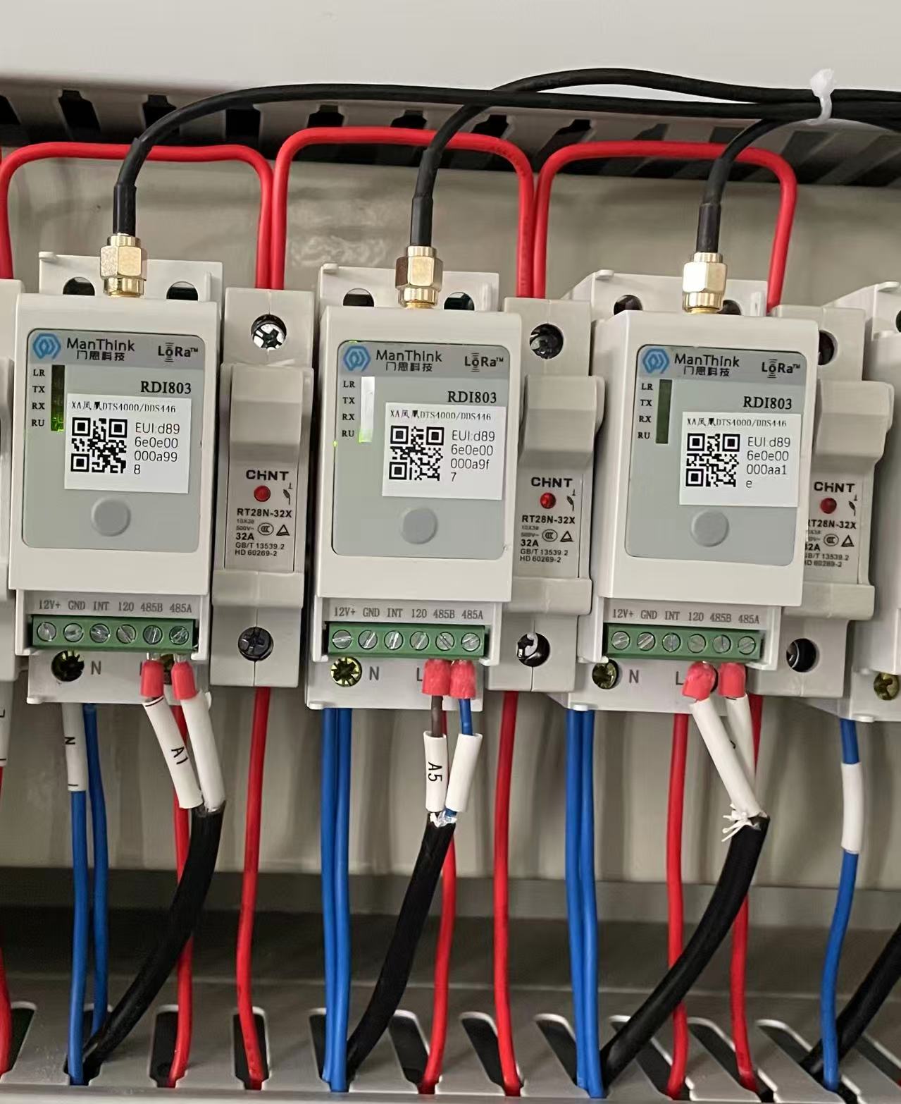
- FIXED EQUIPMENT:clipping the DTU into the guide rail.
- Connect the power supply:correctly connect the neutral and live wires to the power terminals marked "N" and "L.
- Wiring communication:connect the "A" and "B" terminals of your RS485 device to the "485-A" and "485-B" terminals of the DTU respectively.
- Power-on operation:turn on the power supply, observe the status of the indicator light, and start communication after the indicator light indicates stably.
Note:please make sure that the power is disconnected before wiring, and all serial port parameters need to match your terminal equipment.
11. Standard
The format of the communication protocol is customized through EB Compilation. We recommend that you use the protocol format standard recommended by ManThink.
\PTL-D01 ManThink Technology IoT Terminal Application Layer General Protocol V1.5
12. Parameter Modification
Refer to Chapter 5 of PTL-D01-Internet of Things Terminal Application Layer General Protocol V1.3 for parameter modification. Parameter modification is delivered through Port 214.
\PTL-D01 ManThink Technology IoT Terminal Application Layer General Protocol V1.5
12.1 Configuration Parameter Address Table
\AN-25100106 EdgeBus App Parameter Manual
13. ThinkLink Thing Model
Log in to https://thinklink.manthink.cn
13.1 Device Template
Add devices according to the template MT-EB-POWER. The models already mounted under MT-EB-POWER are as follows:
- Thing Model: MT-EB
- RPC:
[MT ACT] action: Used to execute operations such as reset, join, redo, and reading parameters
[MT ACT] transparent: Transparent RPC; hexadecimal data can be sent via port 51, which will be forwarded to sub-devices through the RS485 interface, and responses from the sub-device will be returned
[MT SET] app para: Set EB parameters
[MT ACT] debug modbus: Online Modbus debugging by entering information such as 485 address and Modbus function code
ALARM: Used for alarm functionality; trigger rules must be configured to enable full alarm features
14. Contact Us
Website: www.manthink.cn
Email: info@ manthink.cn
Tel: +86-15810684257