GD71 Indoor LoRaWAN Gateway Manual
Document version: 1.3
1. Product Introduction
2. Product Description
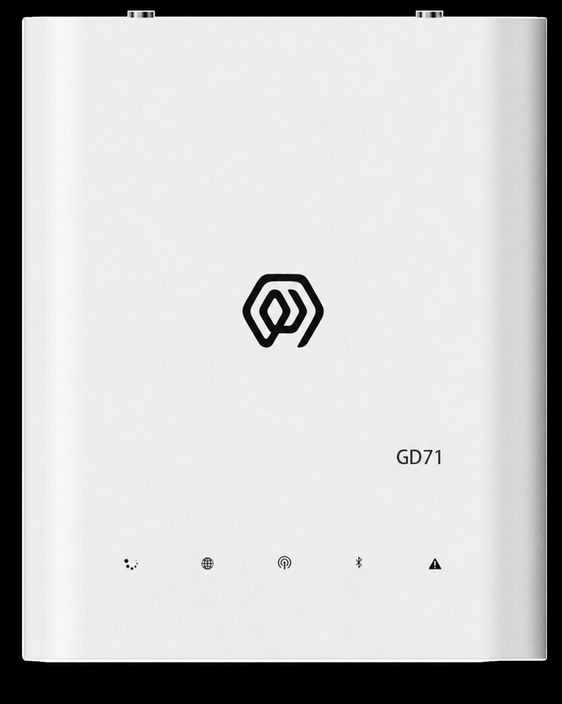
GD71 is an indoor, multi-channel, high-performance gateway designed by ManThink for LoRaWAN systems. It uses a high-performance processor, a Semtech SX1302 LoRa concentrator and an industrial-grade Wi-Fi module. It supports Ethernet, cellular, Wi-Fi access-point/client and Bluetooth Low Energy (BLE) connections. GD71 is suitable for campuses, offices, shopping malls, hotels, factories and other indoor IoT environments, and supports edge computing, protocol conversion, data buffering and local application extensions.
3. Main Features
- High-performance chipset, at least 512 MB DDR and at least 16 GB eMMC
- Semtech SX1302 LoRa concentrator supporting Type A with 8 frequency points and Type D with 16 frequency points
- -141 dBm LoRa receiver sensitivity at SF12/BW 125 kHz; maximum transmit power is 27 dBm for suffix
-1and 22 dBm for suffix-2, with a maximum-power tolerance of ±2 dBm - Standard LoRaWAN and AS923 regional parameters, plus regional configurations for CN470, EU433, EU868, AU915 and US915
- Industrial-grade Wi-Fi module supporting access-point and client modes
- 2.4 GHz or 5 GHz Wi-Fi, IEEE 802.11a/b/g/n/ac/ax, at least 100 Mbps download and at least 50 Mbps upload
- Bluetooth Low Energy (BLE)
- WPA2, AES and TLS
- PoE/PoE+ and USB Type-C power options
- Ethernet, 4G/LTE and Wi-Fi backhaul options, plus dual-gateway redundancy architecture
- GPS/BeiDou positioning and NTP clock synchronization
- MQTT, MQTTS, HTTP, HTTPS, SNMP, DHCP, static IP, NAT and ICMP
- Secure remote management, configuration and upgrades; supports Python and Node-RED for secondary development
- Automatic fault detection and recovery; reporting of CPU, memory, storage, network and LoRa communication-quality indicators
- Built-in indicators for LoRa, network, power/operation and faults
- Built-in TKL, including LoRaWAN network server and IoT platform, historical data, Thing Model and Dashboard
- Wall mounting or freestanding installation, with visual configuration and maintenance through gwTool7
4. Technical Specifications
| Category | Parameter | GD71 Specification |
|---|---|---|
| § Compute and storage | ||
| SoC | High-performance multi-core processor | |
| Memory | DDR, ≥ 512 MB | |
| Storage | eMMC, ≥ 16 GB | |
| § Software and platform | ||
| Built-in platform | Built-in TKL LoRaWAN network server and IoT platform | |
| External platforms/protocols | ThinkLink, ChirpStack, TTN, Basic Station and GWMP | |
| Data services | PostgreSQL, Redis, historical data storage, Thing Model, application data parsing and Dashboard | |
| Secondary development | Supports Python and Node-RED | |
| Remote operations | Remote management, configuration and upgrades over SSH | |
| Fault handling | Automatic fault detection and recovery | |
| Monitoring | Reporting of CPU, memory and storage usage, network status and LoRa communication quality | |
| § LoRaWAN | ||
| Concentrator | Semtech SX1302 | |
| Protocol | Standard LoRaWAN; compliant with LoRa Alliance™ LoRaWAN Specification v1.0.4 or a later version | |
| Operating bands | AS923: 920–928 MHz; regional configurations also include CN470, EU433, EU868, US915 (902–928 MHz) and AU915 | |
| Channels/frequency points | Type A: 8 frequency points; Type D: 16 frequency points at BW = 125 kHz | |
| Demodulators (Type A) | 16, processing up to 16 packets simultaneously | |
| Demodulator composition (Type A) | 8 × SF5–SF12 LoRa® demodulators; 8 × SF5–SF10 LoRa® demodulators | |
| Channel capacity (Type A) | 65 logical channels; each SF, bandwidth and frequency-point combination defines a channel | |
| Communication rate | 292 bps to 15.625 kbps | |
| Spreading factors | SF5 to SF12 | |
| Single-channel bandwidth | 125 kHz or higher | |
| Operating mode (Type A) | Half-duplex | |
| Transmit power | Suffix -1: 27 dBm maximum; suffix -2: 22 dBm maximum; maximum-power tolerance: ±2 dBm | |
| Receiver sensitivity | -141 dBm at SF12/BW 125 kHz | |
| Antenna | Omnidirectional LoRa antenna | |
| § Wi-Fi and Bluetooth | ||
| Wi-Fi module | Industrial-grade Wi-Fi module | |
| Operating modes | Access-point mode and client mode | |
| Bands/standards | 2.4 GHz or 5 GHz; IEEE 802.11a/b/g/n/ac/ax | |
| Download/upload | Download ≥ 100 Mbps; upload ≥ 50 Mbps | |
| Security | WPA2, AES and TLS | |
| Bluetooth | Bluetooth Low Energy (BLE) | |
| § Network and transport | ||
| Ethernet | 1000M/100M; DHCP and static IP configuration | |
| Cellular uplink | CAT1 4G/LTE module by default; LTE-FDD B1/3/5/8 and LTE-TDD B34/38/39/40/41 | |
| Data forwarding | MQTT, MQTTS, HTTP and HTTPS | |
| Network services | NTP, prevailing-version SNMP, NAT and ICMP diagnostics | |
| Network redundancy | Dual-gateway architecture for network redundancy | |
| § Security and authentication | ||
| Device identity | IMEI or device-feature-string authentication | |
| Access protection | Firewall and access control list (ACL) | |
| Transport security | Prevailing-version TLS; administrators can disable unsafe SSH/TLS cipher suites | |
| § Ports and timing | ||
| Configuration ports | USB Type-C, Ethernet and Wi-Fi | |
| SIM slot | One external nano-SIM slot supporting LTE/5G SIM cards; cellular standards are determined by the configured module | |
| Positioning/timing | GPS and BeiDou (BDS) positioning; NTP synchronization | |
| § Power | ||
| PoE power | One PoE or PoE+ Ethernet port; nominal 48 V PoE | |
| USB power | USB Type-C, 5 V | |
| Power consumption | ≤ 5 W in a typical configuration | |
| § Environment and enclosure | ||
| Operating temperature | -N: -20°C to 70°C; -I: -40°C to 70°C; -C: 0°C to 65°C | |
| Operating humidity | 0% to 95% RH, non-condensing | |
| Ingress protection | IP30 | |
| Radio-equipment requirement | Compliant with HKCA 1078 requirements | |
| Weight | 0.3 kg | |
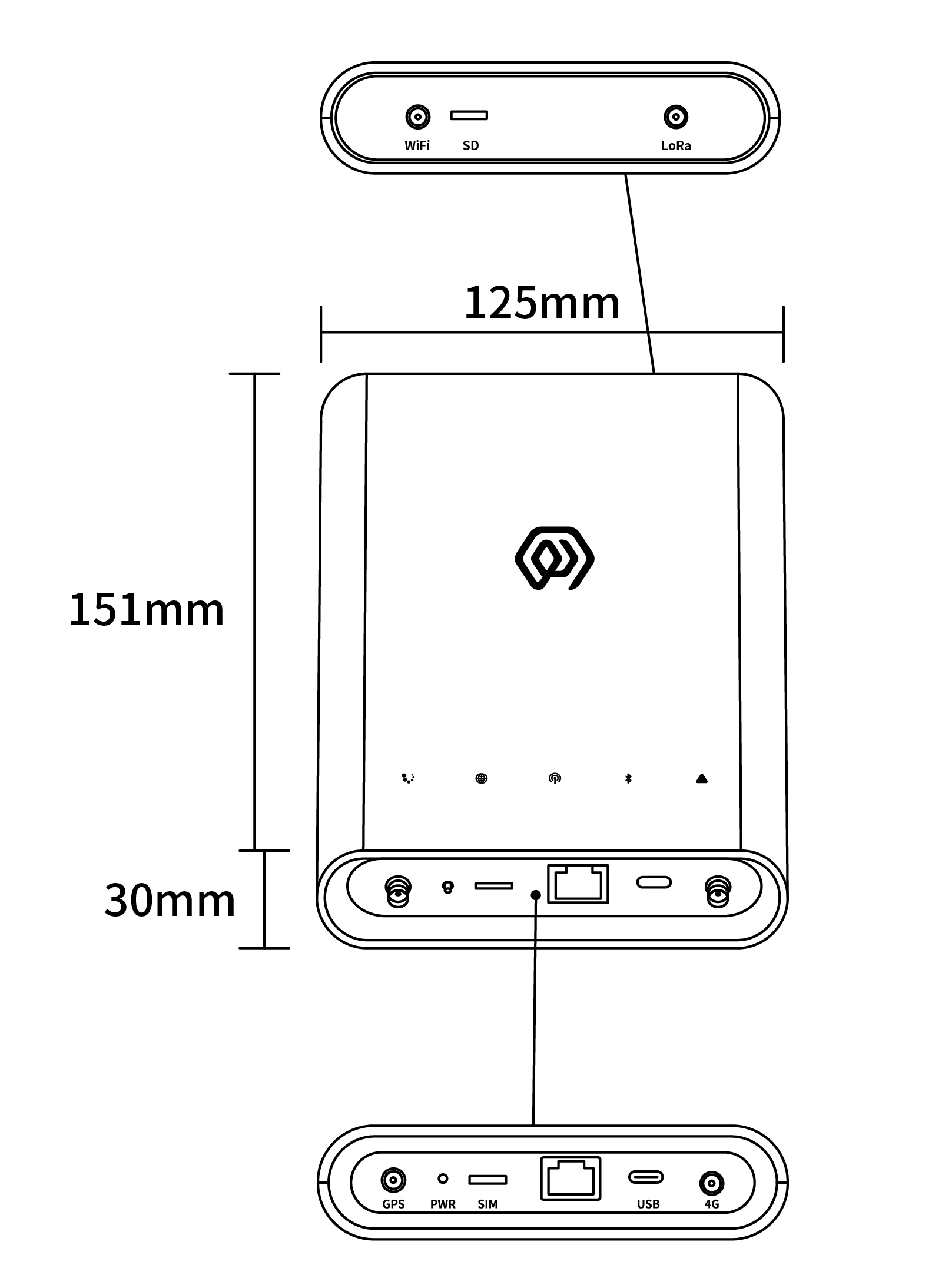
| Dimensions | 151 × 125 × 30 mm | |
| Installation | Wall mounting or freestanding placement |
Cellular deployment note: if local operator bands are outside the default module range, contact ManThink for a suitable cellular module.
5. Accessories
The product package includes the GD71 gateway, PoE power components, power adapter, Type-C cable, mounting backplate, LoRa antenna, LTE antenna, GPS antenna, Wi-Fi antenna, network cable and fasteners. Cellular-enabled versions include an LTE/5G SIM card.
6. Product Dimensions
The product outline and installation dimensions are shown below.
7. Interface Description
| Interface | Description |
|---|---|
| WiFi | Wi-Fi antenna interface |
| SD | Memory-card slot |
| LoRa | LoRa antenna interface |
| GPS | GPS/BeiDou antenna interface |
| PWR | Reset button |
| SIM | nano-SIM slot |
| RJ45 | Ethernet and PoE/PoE+ power interface |
| USB | USB Type-C power, configuration and debugging interface |
| 4G | LTE antenna interface |
8. Indicator Description
| Indicator | Color/network | States and meanings |
|---|---|---|
| Run indicator | — | Steady: System starting. Off: Base startup complete; applications are starting. 1 Hz flashing: Normal operation. |
| Network indicator | Green/wired Blue/cellular | Green, 1 Hz: Wired network normal. Green, every 500 ms: Wired network abnormal. Green, rapid: Network configuration in progress. Blue, off: No cellular module. Blue, steady: Module installed but no SIM. Blue, irregular: Cellular data activity. |
| LoRa transceiver indicator | Green Blue | Green flashing: Transmitting LoRa packets. Blue flashing: Receiving LoRa packets. |
| LAN status indicator | Red Blue | Red: System-control state. Blue: Wi-Fi connection state. |
| Fault indicator | — | Rapid flashing: Startup phase 2. Off: No fault. Flashing: Fault detected. |
9. Product Model
9.1 Standard Model
The GD71 standard model is GD718-AG-AS923-N-2.
An example of a 16-frequency model with an integrated cellular module is GD718-DG-AS923-N-2. A identifies 8 frequency points, D identifies 16 frequency points, and G identifies an integrated cellular module.
The operating temperature range is selected independently of the frequency-point configuration. Select -C, -N or -I in place of the temperature-range segment -N according to the operating-temperature requirements; see Technical Specifications for the ranges.
9.2 Model Components
- GD718: series and RF band. GD71 identifies the indoor LoRaWAN gateway series; 8 identifies the 800 MHz-and-above RF version.
- -AG: LoRa architecture and cellular configuration. A identifies one LoRa antenna, 8 frequency points, 65 channels and half-duplex operation; G identifies an integrated cellular module.
- -DG: LoRa architecture and cellular configuration. D identifies 16 frequency points; G identifies an integrated cellular module.
- -AS923: LoRaWAN regional standard. Identifies support for the AS923 regional parameters.
- -N: Operating temperature is -20°C to 70°C.
- -I: Operating temperature is -40°C to 70°C.
- -C: Operating temperature is 0°C to 65°C.
- -1: transmit-power version. Maximum transmit power is 27 dBm, with a maximum-power tolerance of ±2 dBm.
- -2: transmit-power version. Maximum transmit power is 22 dBm, with a maximum-power tolerance of ±2 dBm.
10. Gateway Installation
Do not open the gateway enclosure during installation. Disconnect power first and verify that antennas, PoE, grounding and cabling meet site requirements.
11. Accessory Connections
11.1 Antenna Connection
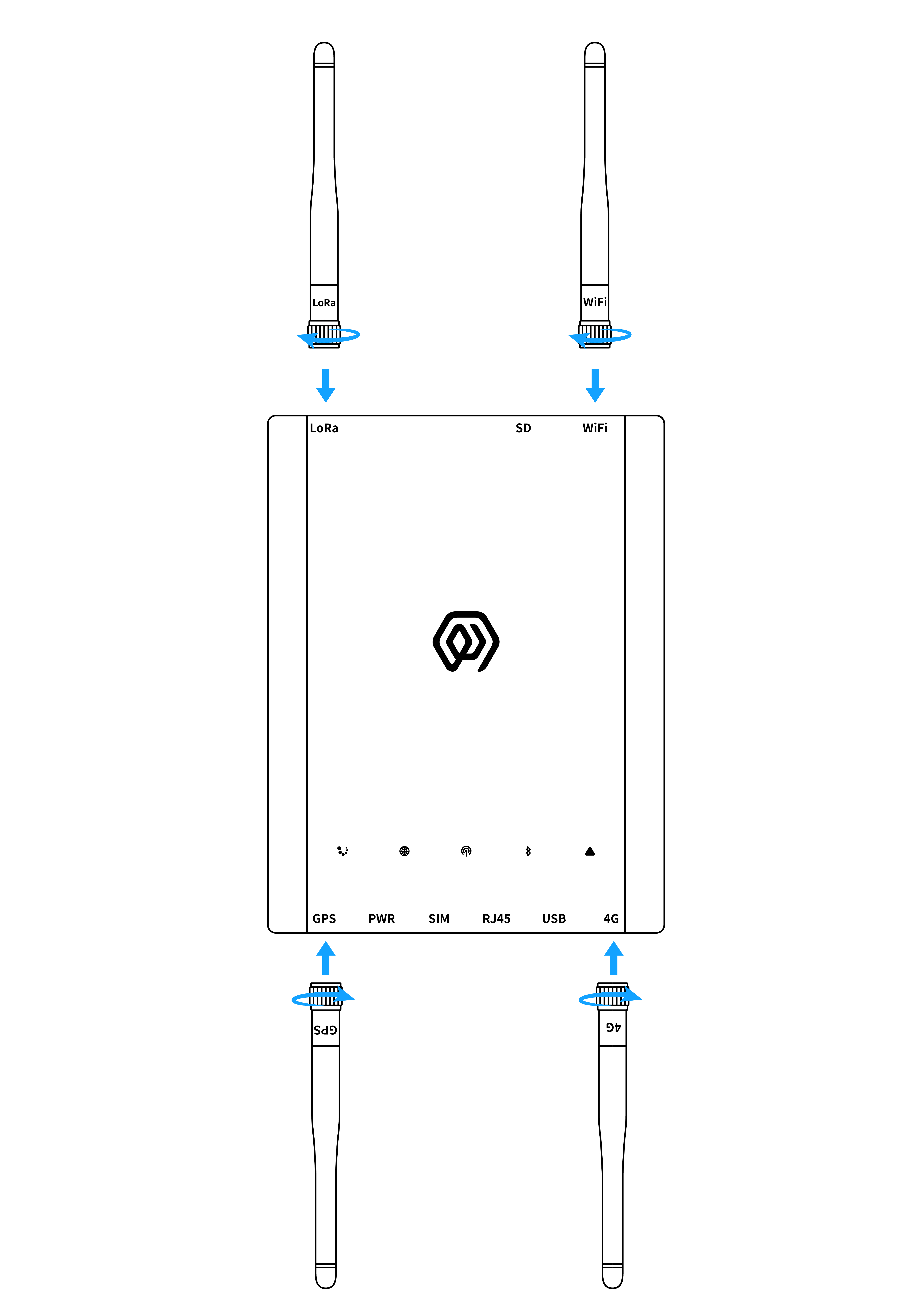
- Connect the LoRa antenna to the LoRa interface.
- Connect the LTE, GPS/BeiDou and Wi-Fi antennas to their matching labeled interfaces.
- Tighten all antenna connectors evenly.
11.2 Type-C Power Connection
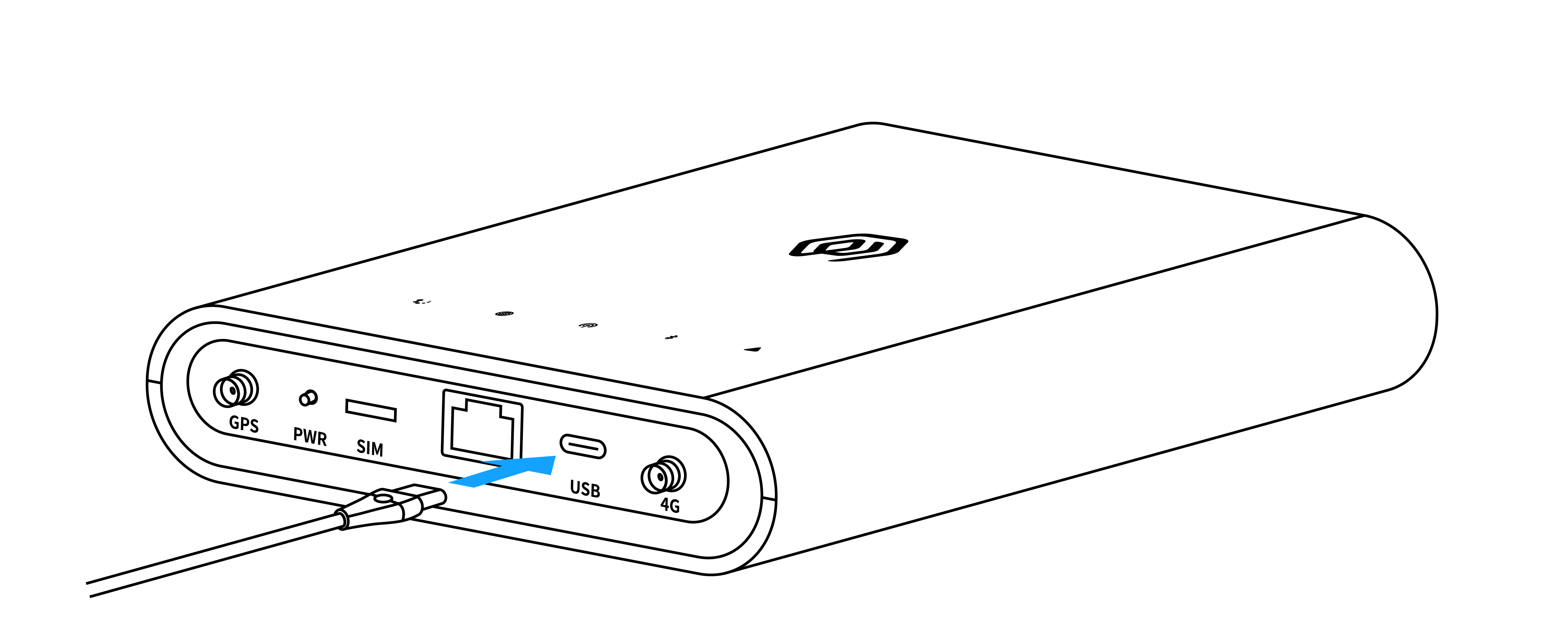
- The Type-C power cable is not required when PoE is used.
- For USB power, connect the Type-C cable to the gateway USB interface.
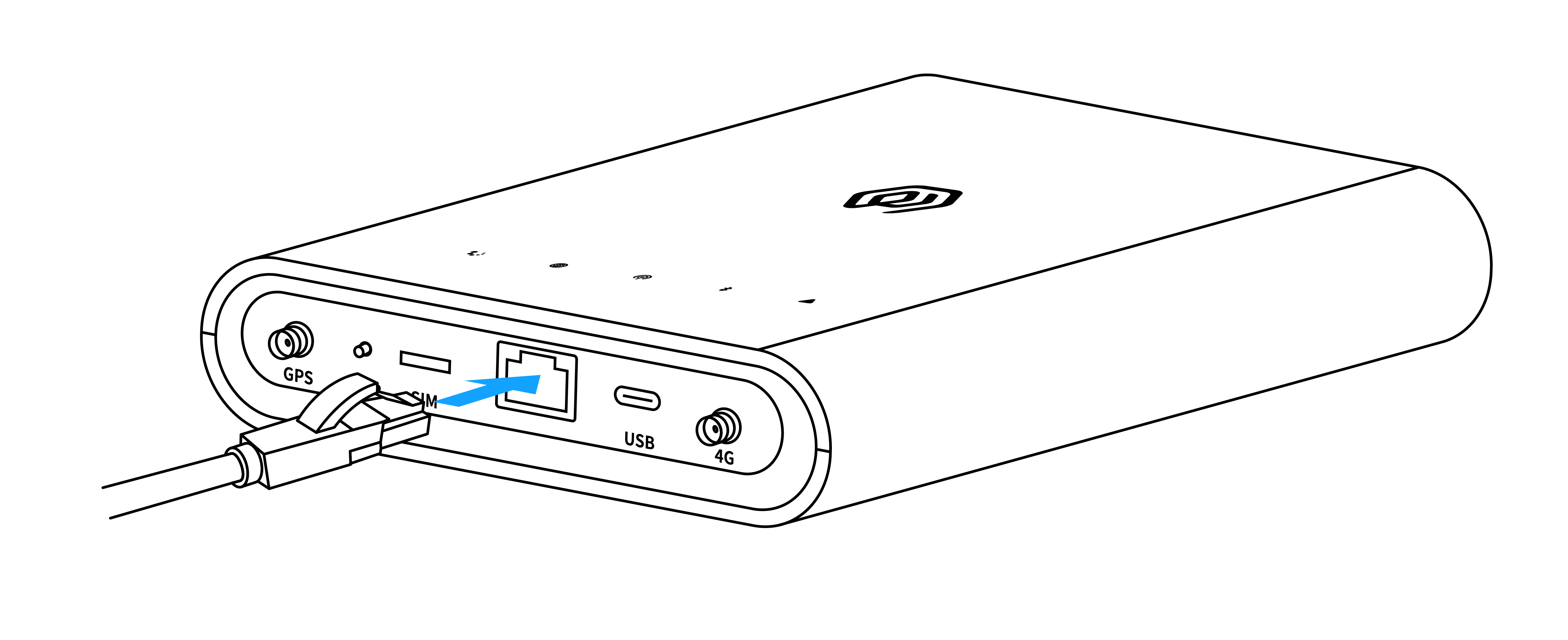
11.3 Network Cable Connection
- Connect the network cable to the gateway RJ45 interface.
- When using PoE/PoE+ power, connect the other end to compliant PoE equipment.
11.4 SIM Card Installation
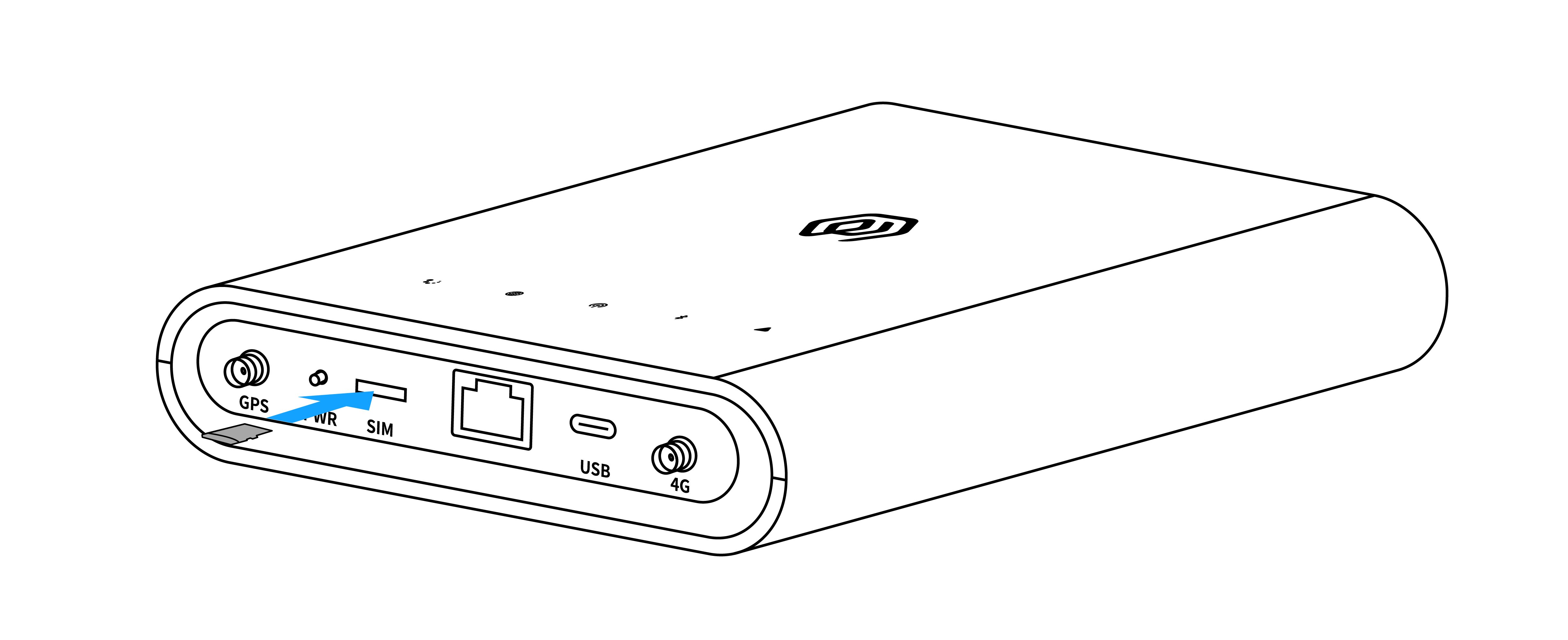
- Before using cellular networking, insert a nano-SIM card into the gateway SIM slot.
- Keep the SIM contacts facing down with the notch in the upper-left corner.

12. Gateway Mounting
12.1 Wall Mounting
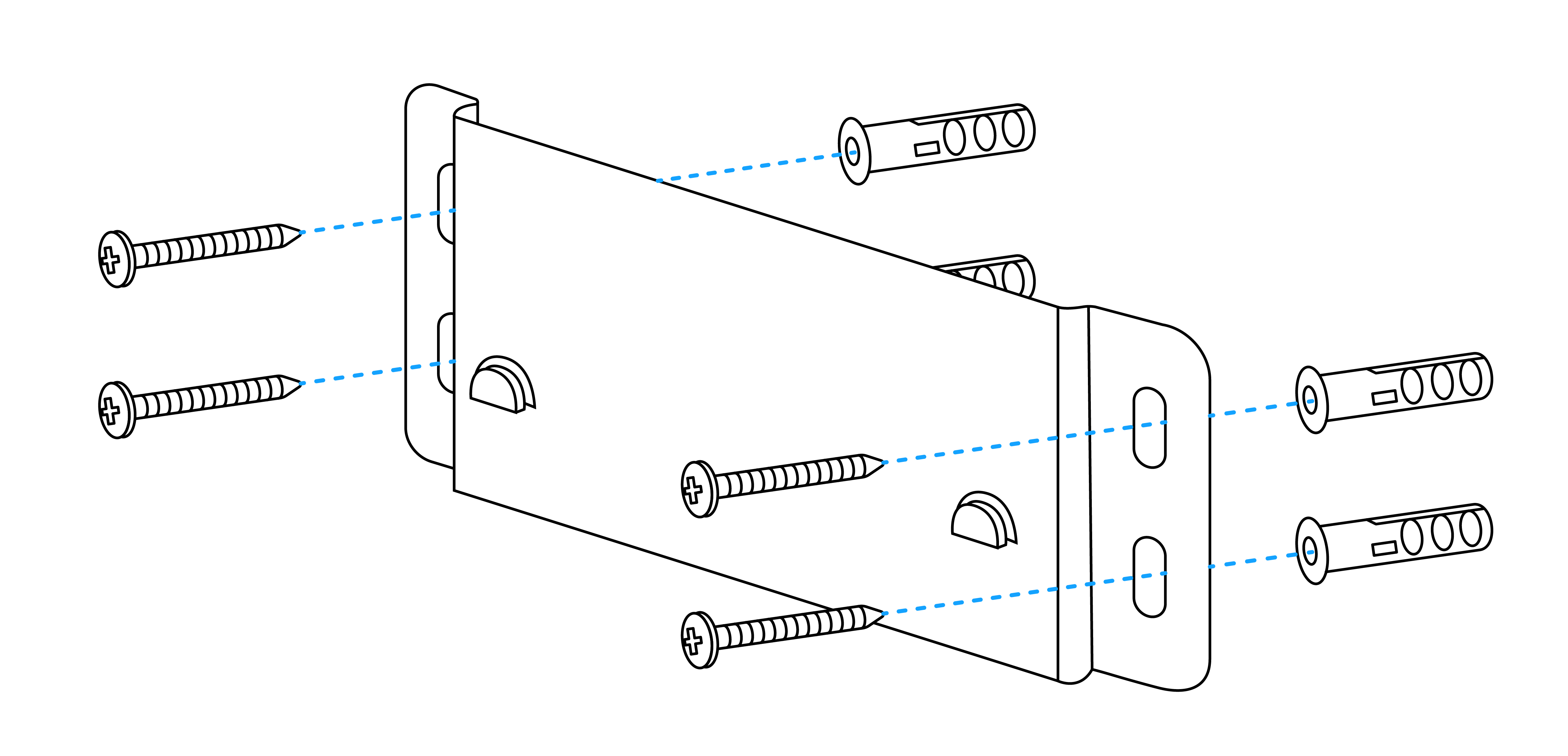
- Mark and drill the wall using the backplate holes, then install anchors suitable for the wall material.
- Fasten the mounting backplate to the wall and tighten the screws evenly.
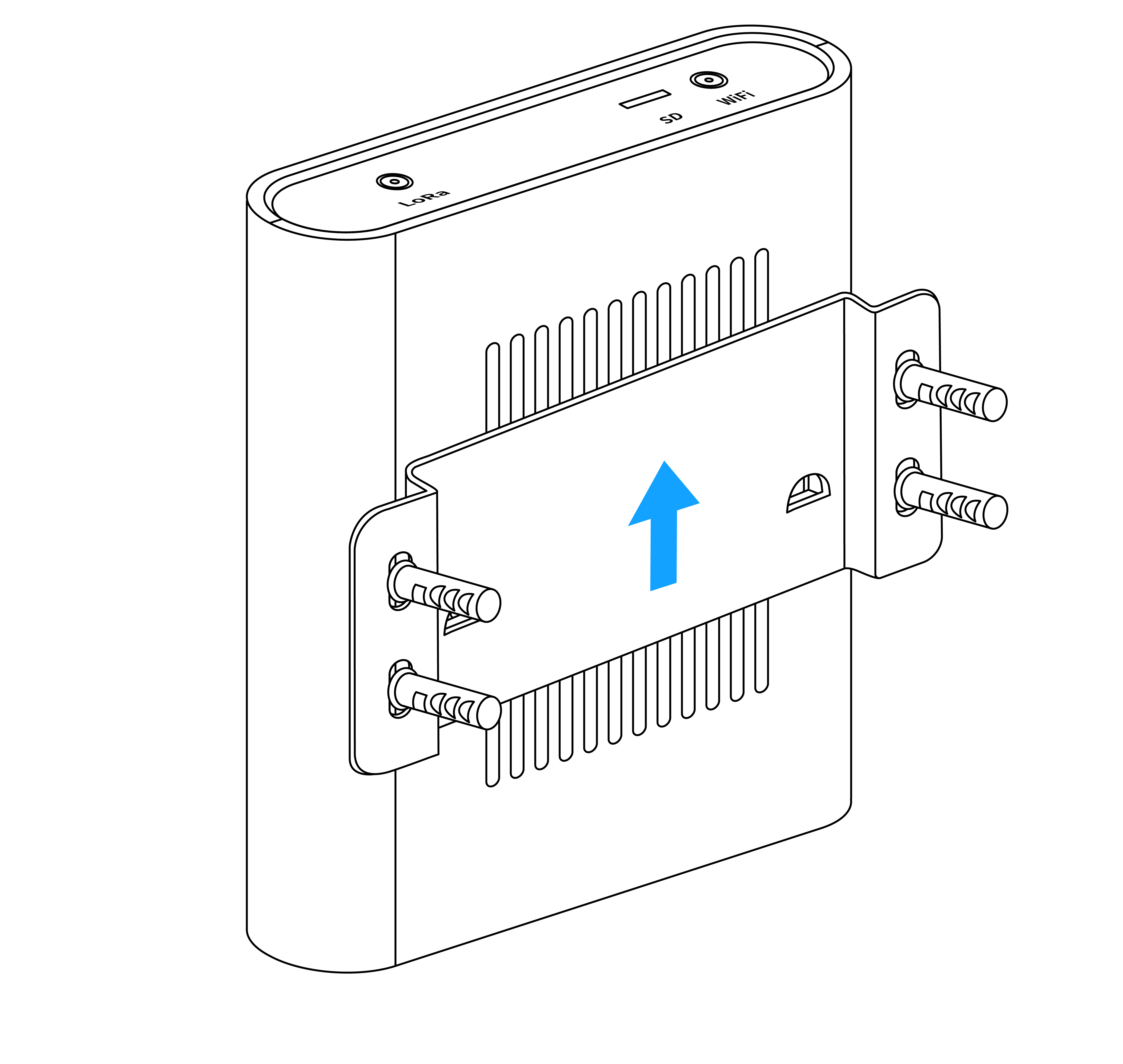
- Engage the gateway rear slots with the backplate and verify that the gateway is secure.
13. Gateway Configuration
GD71 is configured and maintained with gwTool7. See the gwTool7 Gateway Administrator Manual.
14. Platform Connections
- ThinkLink: ThinkLink User Guide
- ChirpStack: Connect with Basic Station (gwTool7)
- TTN: Connect with Basic Station (gwTool7)
15. Security Configuration Recommendations
- Change default administrative credentials during initial deployment and restrict management access to trusted networks.
- Enable the firewall or ACL and disable unnecessary services and ports.
- Use a prevailing TLS version and disable unsafe SSH/TLS cipher suites.
- Retain audit records for remote upgrades, configuration changes and administrator operations.
- Regularly review CPU, memory, storage, network and LoRa communication-quality alarms.
Contact Us
Website: www.manthink.cn
Email: info@manthink.cn
Tel: +86-15810684257