KC25 DIN-Rail RS-485 LoRaWAN Data Logger
1. Product introduction
1.1 Product description
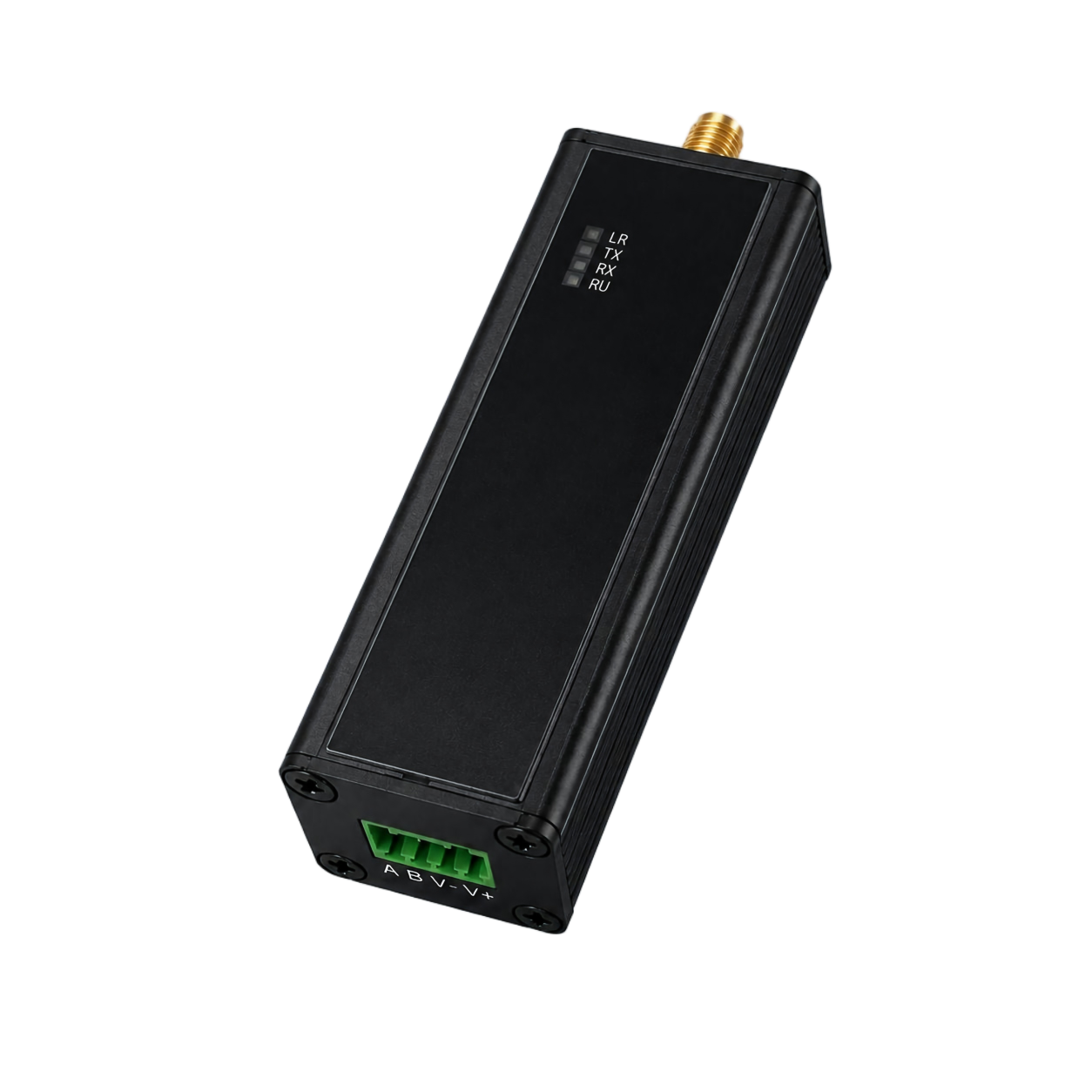
KC25 is a high-performance, low-power and highly configurable data transmission unit (DTU) developed by ManThink. It integrates a high-performance MCU and a LoRa® RF chip, supports the standard LoRaWAN® protocol, and is designed for long-range, low-power communication.
KC25 uses an industrial DIN-rail design and accepts a DC 5–24 V wide-range supply. Its RS-485 interface connects external devices for data acquisition and remote control, while LoRaWAN carries application data to the target platform.
KC25 is compatible with ManThink and third-party LoRaWAN gateways and can connect to ThinkLink, ChirpStack and The Things Network (TTN).
KC25 includes an EdgeBus (EB) virtual machine. EB scripts can be compiled into firmware and deployed remotely through FUOTA. The virtual machine can implement RS-485 protocol parsing, COV reporting, alarm triggers and data restructuring at the edge.
1.2 Applications
- Industrial sites
- Electricity-meter reading
- Hydrometeorological monitoring
- Environmental and municipal monitoring
1.3 Main features
- RS-485 interface
- DC 5–24 V input
- Built-in EB virtual machine
- FUOTA over LoRaWAN
- ThinkLink, ChirpStack and TTN support
- CN470, EU433, EU868, AS923, AU915 and US902 regional standards
- Compatible with RS-485-based communication protocols
2. Specifications
2.1 Interface overview
| Parameter | Specification |
|---|---|
| Connector | 2.54 mm terminal block |
| Connections | 4 |
| Indicators | Four: RU, LR, TX and RX |
2.2 Technical specifications
2.2.1 Wireless
| Parameter | Specification |
|---|---|
| Protocol | Standard LoRaWAN® protocol |
| Regional standards | CN470 / EU433 / EU868 / AS923 / AU915 / US902 |
| Transmit power | Up to 22 dBm, configurable |
| Receive sensitivity | -142 dBm at SF12, BW 125 kHz |
| Activation and operating mode | OTAA / ABP, Class C |
2.2.2 Protocol and configuration
| Parameter | Specification |
|---|---|
| Button actions | Short press to query and upload data; hold for 6–8 seconds to trigger network join |
| Parameter configuration | Downlink commands from the Network Server |
2.2.3 Physical
| Parameter | Specification |
|---|---|
| Power input | DC 5–24 V |
| Receive current | < 8 mA |
| Transmit current | < 110 mA at 22 dBm |
| Operating temperature | -40°C to 85°C |
| Relative humidity | ≤ 95%, non-condensing |
| Ingress protection | IP53 |
| Material and color | Aluminum alloy, black |
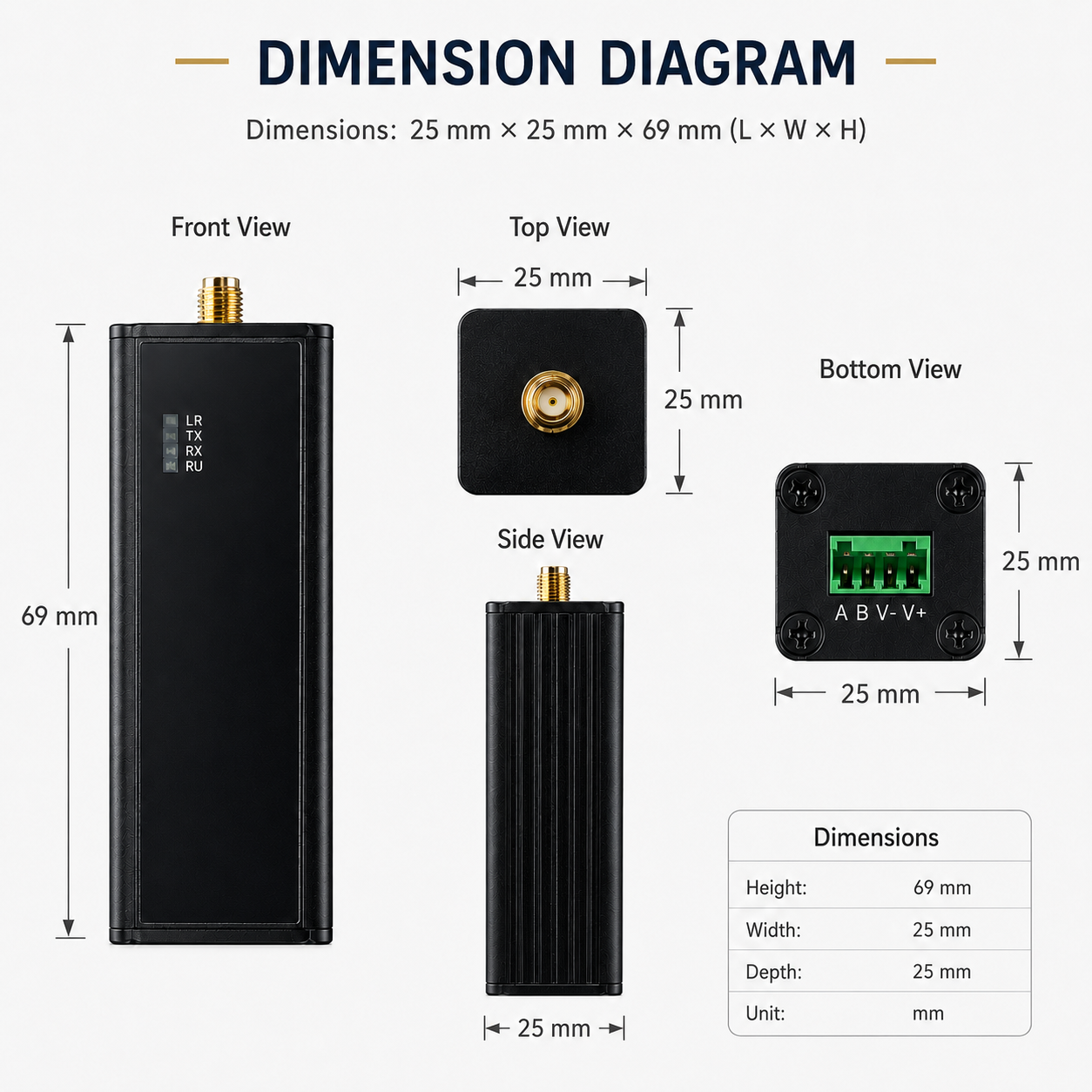
| Dimensions | 69 mm × 25 mm × 25 mm |
| Mounting | DIN rail |
3. Dimensions and interfaces
3.1 Dimensions
3.2 Interface definition
| Name | Definition |
|---|---|
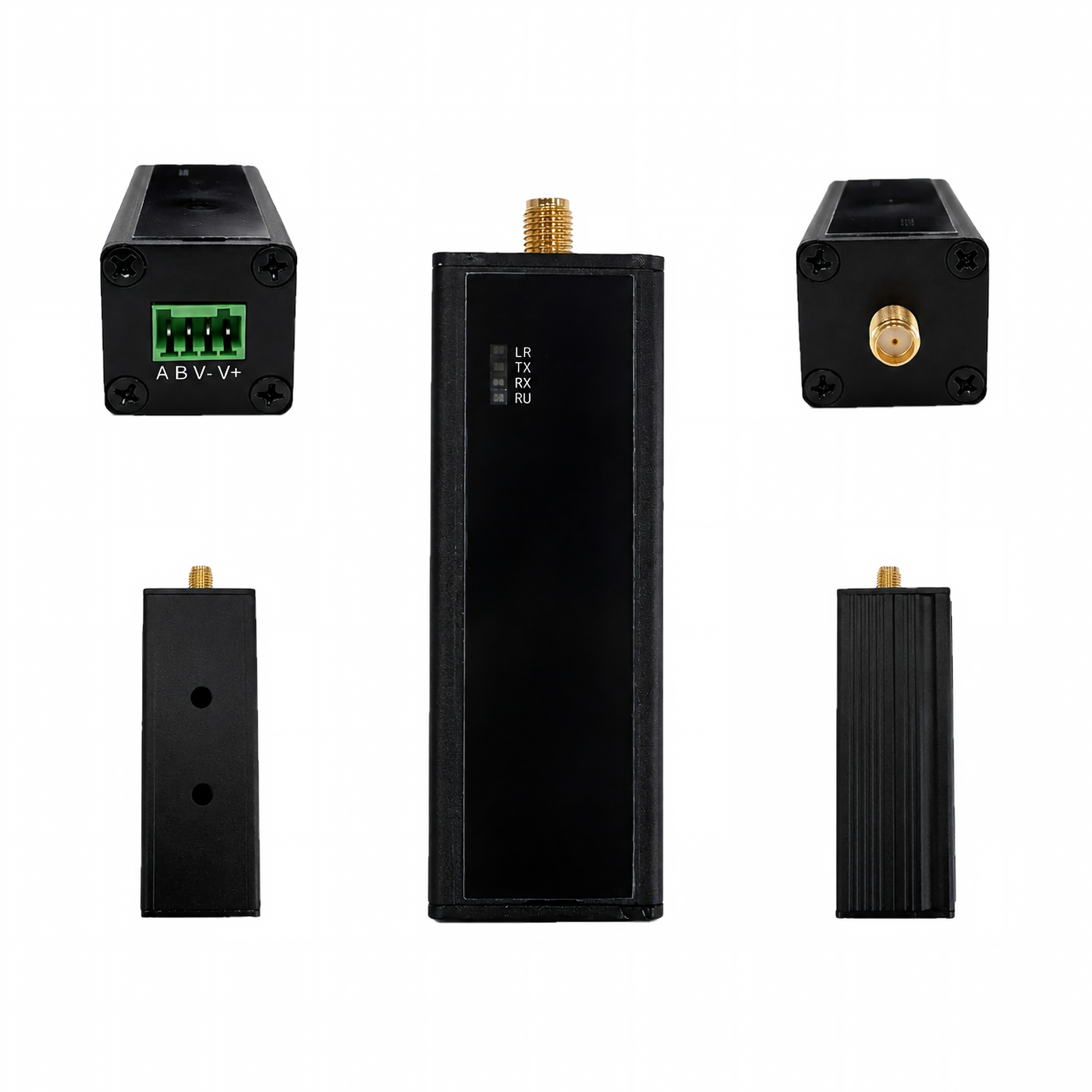
| A | RS-485 A |
| B | RS-485 B |
| V+ | Positive DC input |
| V- | Negative DC input / GND |
| Trigger button | Short press to query and upload data; hold for more than 6 seconds to trigger network join |
| RU | System-run indicator; flashes once per second during normal operation |
| LR | LoRaWAN data indicator; flashes for approximately 100 ms when data is transmitted or received |
| TX | RS-485 transmit indicator; flashes while sending data |
| RX | RS-485 receive indicator; flashes while receiving data |
| Threaded connector | LoRa antenna connector |
4. Product model
4.1 Model example
KC258-A2-AS923-N
4.2 Model component breakdown
KC258: product series and RF band.KC25identifies a second-generation DIN-rail RS-485 DTU.8identifies the 800 MHz-and-above RF version for EU868, AS923, AU915 and US902.- Other band option:
4identifies the 400 MHz RF version for EU433 and CN470.
-A2: hardware and power configuration.Aidentifies the default hardware configuration.2identifies DC 5–24 V input.- Other power option:
1is a blank position.
-AS923: LoRaWAN regional standard.AS923means that the device supports the LoRaWAN AS923 regional parameters.- Other regional codes are
CN470,EU433,EU868,AU915andUS902;US902denotes the LoRaWAN US915 (902–928 MHz) regional parameters.
-N: default version.Nidentifies the default version.- Other values are reserved for customized or special versions.
4.3 Complete model meaning
The complete meaning of KC258-A2-AS923-N is:
This is a second-generation DIN-rail RS-485 DTU in the 800 MHz-and-above RF class. It uses the default hardware configuration, accepts DC 5–24 V input, supports the LoRaWAN AS923 regional standard, and uses the default final version code N.
5. Instructions for use
5.1 Network topology
KC25 is a standard LoRaWAN end device and requires a LoRaWAN gateway and LoRaWAN Network Server. It can use a ManThink or third-party gateway and connect to standard LoRaWAN networks such as ThinkLink, ChirpStack and TTN.

5.2 Operating modes
5.2.1 Configure acquisition and upload tasks with EB
KC25 includes an EB virtual machine. The SDK and TypeScript can implement meter-reading and other acquisition logic. See EdgeBus Compiler.
5.2.2 Communication test
Short-press the trigger button to query data and send one uplink packet.
5.2.3 Network join
Hold the trigger button for 6–8 seconds to trigger a new network join.
5.3 Installation
- Mount the device: Snap KC25 onto the DIN rail.
- Connect power: With power removed, connect the positive DC lead to
V+and the negative lead toV-. - Connect RS-485: Connect the external device's A and B terminals to the corresponding
AandBterminals on KC25. - Power on: Apply power and check the indicators. Start communication after RU flashes normally.
Wiring safety
Disconnect power before wiring. The supply must remain within DC 5–24 V, and all RS-485 serial parameters must match the connected device.
6. Communication protocol and parameters
6.1 Communication protocol
The application protocol is customized through EB compilation. The format defined in “PTL-D01 ManThink IoT Terminal Application-Layer General Protocol V1.5” is recommended.
6.2 Parameter changes
Follow Chapter 5 of PTL-D01 and send parameter changes through port 214. See EdgeBus App Parameters for the EB parameter-address table.
7. ThinkLink thing model
Sign in to ThinkLink and add the device with template MT-EB-POWER. The template uses thing model MT-EB and includes:
[MT ACT] action: Run reset, join, redo, parameter-read and related operations.[MT ACT] transparent: Send hexadecimal data through port 51, forward it to a child device over RS-485 and return the response.[MT SET] app para: Set EB parameters.[MT ACT] debug modbus: Debug Modbus online by entering the RS-485 address and Modbus function code.ALARM: Alarm function; trigger rules must be configured.
8. Contact us
- Website: www.manthink.cn
- Email: info@manthink.cn
- Tel: +86-15810684257