GDI52 Indoor gateway userguide
Document version: 1.1
Language-version note: The Chinese manual additionally states that GDI52x does not support GPS and that installation does not require opening the enclosure. The Chinese and English manuals also differ on fast network-indicator flashing: English says no 4G module is installed; Chinese says the network is being configured. Confirm behavior against the current hardware revision or with technical support before service work.
1. Product Introduction
1.1 Product Introduction
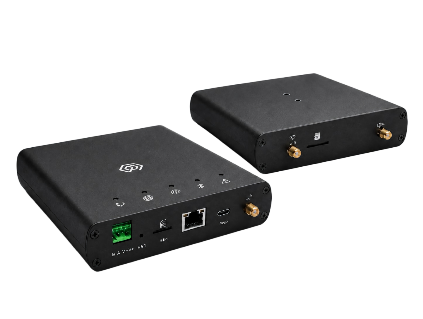
GDI52x is a new-generation indoor gateway product designed by ManThink for LoRaWAN systems.
GDI52x inherits the core functional architecture of GDI51x. Based on a high-performance LoRaWAN gateway design, it supports LoRaWAN network access, ThinkLink platform integration, and third-party LoRaWAN Network Servers. It is suitable for IoT application scenarios including industrial parks, buildings, industrial sites, and smart property management.
Compared with GDI51x, GDI52x adopts an aluminum alloy enclosure design, improving structural strength and industrial appearance. The gateway adds an RS-485 communication interface and supports DC 5-24V wide-range power input.
1.2 Product Features
Supports ThinkLink, ChirpStack, TTN and other LoRaWAN platforms
Supports Basic Station and GWMP gateway protocols
Built-in ThinkLink (TKL) platform for edge data processing and management
Supports historical data storage
Supports device models and application data parsing
Supports Dashboard visualization
Supports 4G, WiFi and Ethernet backhaul
Supports RS-485 field device connection
Supports DC 5-24V power supply
Supports remote maintenance and upgrade
Provides Web configuration interface
8 frequency channels (BW=125kHz)
16 LoRa demodulators for concurrent packet processing
65 configurable channels
Maximum TX power: suffix
-2, 22 dBm maximumRX sensitivity: -141dBm (SF=12, BW=125kHz)
Supports US902, AU915, AS923, EU868, EU433 and CN470 LoRaWAN regions
Aluminum alloy industrial enclosure
2. Specifications
2.1 Parameters
| SOC | * LS1012A 64-bit ARM Cortex-A53 800MHz 2W |
|---|---|
| Memory | * Support DDR3L 1066 MHz * Memory:512MB |
| Storage | * ≥ 16 GB eMMC |
| Software | * Built-in NS and IoT platform (with integrated TKL) * Supports ThinkLink, ChirpStack, TTN, Basic Station, and GWMP protocols * Supports PostgreSQL and Redis databases * Supports historical data storage and Leaf mode * Supports Thing Model and application data parsing * Supports Dashboard |
| LoRa | * Working frequency band: CN 470 470M ~ 510MHz EU868 863M~870MHz EU433 433M~434MHz AS923 920M~928MHz US902 902M-928 MHz AU915 915M-928 MHz · Communication Rate: 292bps to 15.625kbps, supports SF5 to SF12 · Transmit Power: suffix -2, 22 dBm maximum · Receiver sensitivity: -141 dBm (SF = 12, BW = 125 kHz) · Antenna Type: Omnidirectional · Frequency points: 8 (BW = 125 kHz) · Demodulators: 16, capable of processing 16 packets simultaneously(8 × SF5-SF12 LoRa® demodulators; 8 × SF5-SF10 LoRa® demodulators) · Channels: 65 (each channel is defined by a unique combination of SF, BW, and frequency point; BW = 125 kHz, totaling 65 channels) · Operating Mode: Half-duplex · Single Channel Bandwidth: 125KHz or higher |
| Data Backhaul | · Ethernet: 1000M/100M · 4G Note : The Gateway uses 4G uplink by default, CAT1 module, and supports the following frequency bands:LTE-FDD: B1/3/5/8;LTE-TDD: B34/38/39/40/41 If the frequency band used by the planned regional operator is not in the above frequency band, please contact the technical personnel of ManThink to replace the applicable 4G module. |
| Configure Ports | · USB-TypeC · Ethernet · WiFi |
| Power Supply | · POE(48V) · USB TYPE-C(5V) · DC 5-24V |
| Power Consumption | · 5W |
| Environmental Parameters | · Working temperature:-20 ℃ ~ 65 ℃ · Working humidity: 0% ~ 95% RH · Waterproof and dustproof: IP53 |
| Weight | 0.33kg |
| Dimensions | 139mm x 122mm x 28mm |
| Installation Method | Rail mounting |
2.2 Product size
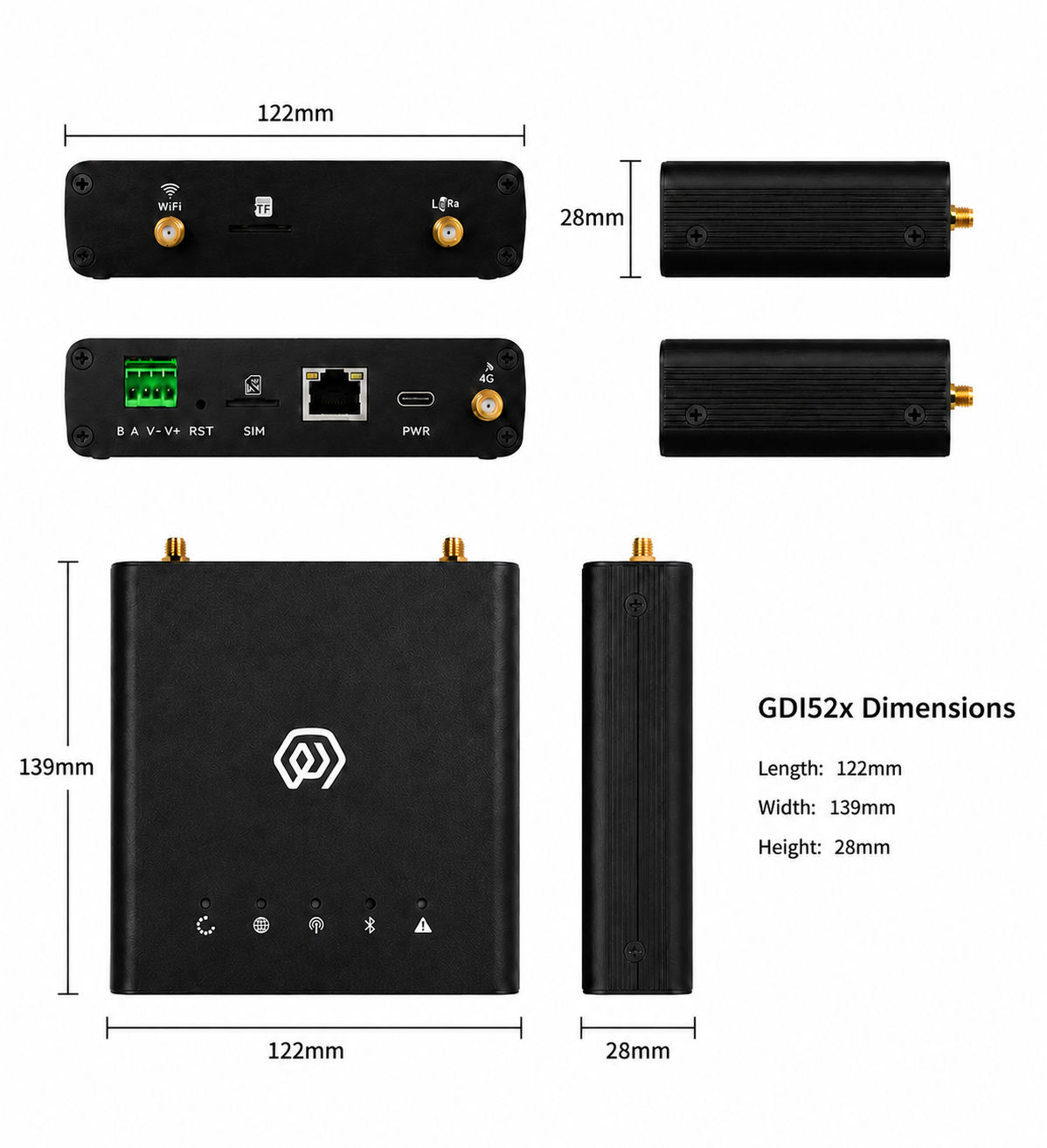
2.3 Interface Description
| Interface Name | Description |
|---|---|
| WiFi | WIFI antenna interface |
| TF | Memory card slot |
| LoRa | LoRa Antenna interface |
| B A V- V+ | RS485 interface/DC5-24V power supply |
| RST | Reset key |
| SIM | SIM card slot |
| RJ45 | Network cable interface (POE power supply) |
| PWR | Type-C interface |
| 4G | 4G Antenna Interface |
2.4 Indicator Description
| Indicator | Function | Status | Description |
|---|---|---|---|
 | Running Indicator | Steady On | System starting up |
| Off | System running normally, entering process startup phase | ||
| Flashing at 1Hz | System running normally | ||
 | Network Indicator | Red (Wired Network Status) — Flashing at 1Hz | Network connection normal |
| Flashing at 500ms | Network connection abnormal | ||
| Fast Flashing | Gateway does not have 4G module installed | ||
| Blue (4G Network) — Off | Gateway does not have 4G module installed | ||
| Steady On | Gateway has 4G module installed but no SIM card inserted | ||
| Irregular Flashing | Gateway is performing data interaction | ||
 | LoRa Data Transceiver Indicator | Red — Flashing | Gateway is sending a data packet |
| Blue — Flashing | Gateway is receiving a data packet | ||
 | LAN Status Light | Red | System control |
| Blue | WiFi connection status | ||
 | Fault Indicator | Fast Flashing | Second phase of startup process |
| Off | No fault | ||
| Flashing | Fault |
2.5 Product Model
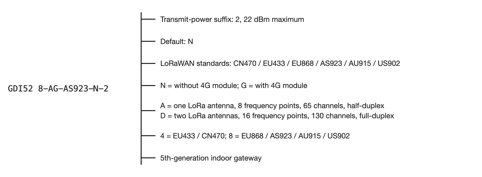
The final model digit -2 identifies a maximum transmit power of 22 dBm.
3. Gateway Installation
3.1 Accessories Connection
3.1.1 Antenna connection
- tighten the LoRa, WiFi and 4G antennas to the corresponding interfaces respectively (LoRa, WiFi and 4G antennas are suction cup antennas)
3.1.2 Type-C power cord connection
when using POE power supply mode, the power cord does not need to be connected
connect the Type-C power cord to the Gateway PWR interface (Type-C interface)
3.1.3 Network cable connection
connect the network cable to the Gateway RJ45 interface
this interface can accept POE power supply
3.1.4 SIM card installation
no need to insert SIM card when connecting network cable
insert SIM card into Gateway SIM interface
note: the direction of SIM card insertion is, the chip is downward, and the notch is in the upper left corner.
3.1.5 RS485 connection
- B A port connected to the green terminal
3.1.6 DC5-24V supply connection
- V- V + port connected to green terminal
3.2 Gateway Installation
3.2.1 Guide rail installation
screw the Gateway accessory rail backplane to the back of the Gateway
install the rail back plate card in the rail
4. User Guide
4.1 Gateway Configuration
gwTool7 Gateway Administrator Manual
4.2 Using ThinkLink
4.3 Connecting to Chirp Stack
Connect to ChirpStack with Basic Station (gwTool7)
4.4 Connecting to TTN
Connect to TTN with Basic Station (gwTool7)
5. Contact Us
Website: www.manthink.cn
Email: info@manthink.cn
Tel: +86 15810684257